
The moment of inertia of a beam section, more precisely its second moment of area (I), measures how stiff that shape is in bending. For a rectangle b wide and h deep it is I = bh³ / 12 about the horizontal axis through the centroid, so a 300 × 600 mm beam has I = 5.4 × 10⁹ mm⁴. Depth is cubed: double the depth and I goes up eight times.
It matters because bending stress is σ = My / I and every beam deflection formula divides by EI. Twice the I means half the deflection. Below are the formulas for common shapes, the parallel axis theorem, and four worked examples.
You can check any of these numbers with the free section properties calculator. It uses the same axes as this page, and every worked answer below matches its output.
What the second moment of area measures
Split a cross-section into tiny pieces of area dA, multiply each by the square of its distance y from the bending axis, and add them up: I = ∫ y² dA. Area far from the axis counts for a lot; area near it counts for almost nothing.
- Bending stress:
σ = M·y / I. For a given moment M, a larger I gives a lower stress. - Deflection: elastic beam formulas divide by EI, the flexural rigidity. A simply supported beam under a uniform load w deflects
δ = 5wL⁴ / (384EI)at midspan, so doubling I halves the deflection.
E belongs to the material; I belongs only to the shape.
Not the same as mass moment of inertia
In dynamics, moment of inertia means ∫ r² dm: how hard a body is to spin up, in kg·m², used for flywheels and rotors. The structural quantity uses area instead of mass, so it is purely geometric, in mm⁴. If the units are kg·m², it is the mass version. The polar moment J = Ix + Iy is a third relative, used for twisting of circular shafts.
Units and conversions
Work in millimetres by hand. The numbers get large, so tables scale them.
| Unit | Equals | Where you meet it |
|---|---|---|
| mm⁴ | base unit | Hand calculations, the section properties calculator |
| 10⁶ mm⁴ | 1,000,000 mm⁴ | Australian steel section tables |
| cm⁴ | 10⁴ mm⁴ | European section tables |
| m⁴ | 10¹² mm⁴ | Frame analysis input, EI in kN·m² |
| in⁴ | 416,231 mm⁴ | US tables and textbooks |
The 300 × 600 mm beam has I = 5.4 × 10⁹ mm⁴. That is 5,400 × 10⁶ mm⁴, 540,000 cm⁴, 0.0054 m⁴ or 12,974 in⁴. The mm⁴ to m⁴ factor is 10¹² because the length factor of 1,000 is raised to the fourth power.
Moment of inertia formulas for common sections
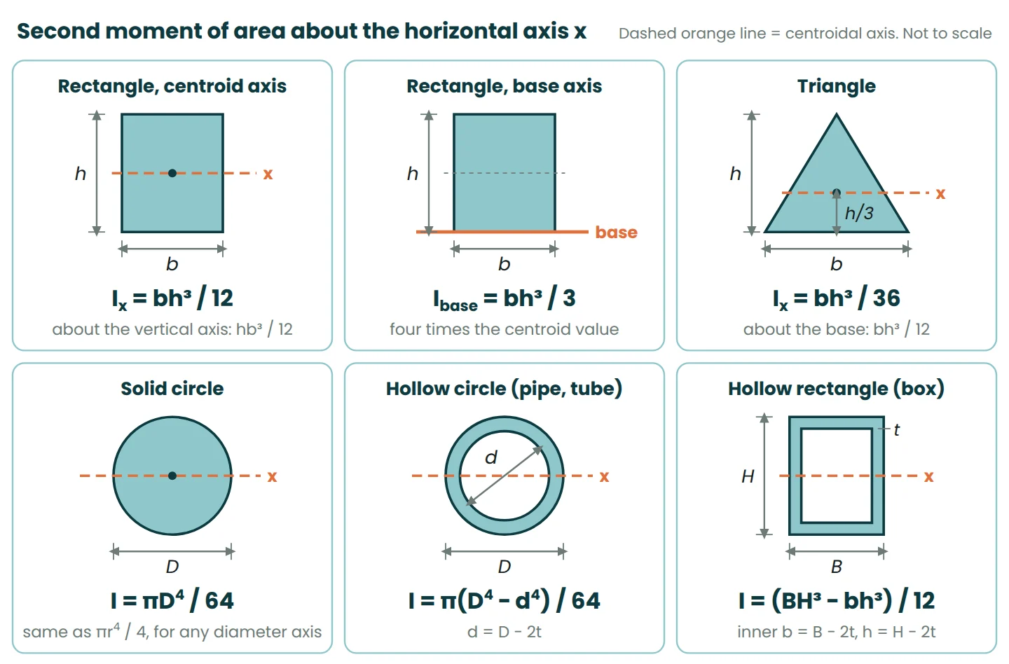
The cubed dimension is always the one at right angles to the bending axis: the depth h for a beam bending the usual way.
- Rectangle about its centroid:
Ix = bh³ / 12, and about the vertical axisIy = hb³ / 12. - Rectangle about its base:
I = bh³ / 3, four times the centroidal value. - Triangle (base b, height h): the centroid is h/3 above the base.
Ix = bh³ / 36about the centroid andbh³ / 12about the base. - Solid circle of diameter D:
I = πD⁴ / 64(orπr⁴ / 4with the radius) about any diameter. - Hollow circle (pipe or tube):
I = π(D⁴ − d⁴) / 64, where d = D − 2t. - Hollow rectangle (box) with a uniform wall:
I = (BH³ − bh³) / 12, where b = B − 2t and h = H − 2t.
Subtracting the hole works because it shares the outer shape’s centroid. An off-centre hole needs the parallel axis theorem.
The parallel axis theorem
Most real sections are built from rectangles. The parallel axis theorem moves each piece’s I from its own centroid to the axis you need: I = Ic + A·d², where Ic is the piece’s second moment of area about its own centroidal axis, A is its area and d is the distance between the two parallel axes.
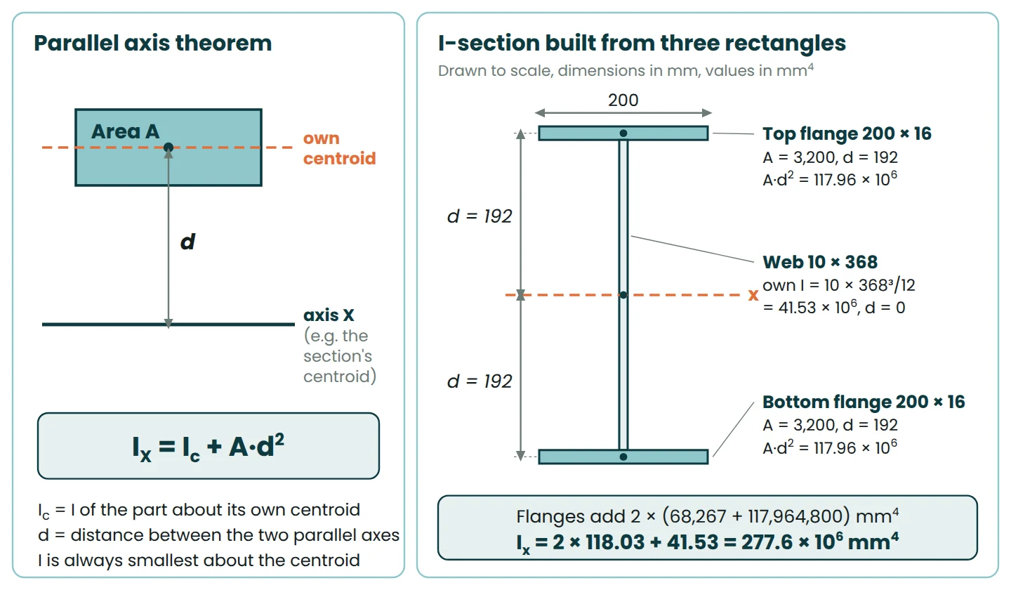
A quick check with the rectangle about its base: bh³/12 + bh × (h/2)² = bh³/12 + bh³/4 = bh³/3, which matches the formula above. For the triangle, bh³/36 + (bh/2) × (h/3)² = bh³/12, also correct.
Ic must be about the piece’s own centroid. Because A·d² is never negative, the centroidal axis always gives the smallest I. To move between two non-centroidal axes, go back through the centroid: subtract A·d₁², then add A·d₂².
Worked examples
Example 1: a 300 × 600 mm rectangular beam
- Area: A = 300 × 600 = 180,000 mm².
- Strong axis: Ix = 300 × 600³ / 12 = 5.40 × 10⁹ mm⁴.
- Weak axis: Iy = 600 × 300³ / 12 = 1.35 × 10⁹ mm⁴.
- About the soffit: I = 300 × 600³ / 3 = 21.6 × 10⁹ mm⁴.
- Section modulus: Zx = bh² / 6 = 18.0 × 10⁶ mm³. Radius of gyration: rx = h / √12 = 173.2 mm and ry = 86.6 mm.
Lay the beam on its side and I drops to 1.35 × 10⁹ mm⁴, a quarter of the upright value. It deflects four times as much, and Z halves to 9.0 × 10⁶ mm³, so bending stress doubles. Same weight, different orientation.
The beam calculator asks for EI in kN·m². With I = 0.0054 m⁴ and E = 30 GPa (30 × 10⁶ kN/m²) for illustration, EI = 162,000 kN·m², and a 20 kN/m load on an 8 m simple span deflects 6.6 mm by 5wL⁴ / 384EI. That is the gross, uncracked section. Reinforced concrete cracks in tension, so AS 3600 uses a smaller effective second moment of area for deflection checks. Treat the gross figure as the best case.
Example 2: a hollow circular tube
Take a steel tube with outside diameter D = 114.3 mm (the outside diameter of DN100 pipe) and wall thickness t = 6.0 mm.
- Inside diameter: d = 114.3 − 2 × 6.0 = 102.3 mm.
- D⁴ = 170.68 × 10⁶ mm⁴ and d⁴ = 109.52 × 10⁶ mm⁴.
- I = π × (170.68 − 109.52) × 10⁶ / 64 = 3.00 × 10⁶ mm⁴.
- A = π × (114.3² − 102.3²) / 4 = 2,041 mm².
- Z = I / (D/2) = 3.00 × 10⁶ / 57.15 = 52.5 × 10³ mm³, and r = √(I/A) = 38.3 mm.
Put the same 2,041 mm² into a solid round bar and its diameter is 51.0 mm, with I of only 0.33 × 10⁶ mm⁴. The tube is about 9 times stiffer and 4 times stronger in bending for the same weight.
Example 3: a symmetric I-section from three rectangles
The section is 400 mm deep with two 200 × 16 mm flanges and a 10 mm web, 368 mm high. Measure y from the underside:
| Part | Size (mm) | A (mm²) | y (mm) | A·y (mm³) | I own (mm⁴) | d (mm) | A·d² (mm⁴) |
|---|---|---|---|---|---|---|---|
| Top flange | 200 × 16 | 3,200 | 392 | 1,254,400 | 68,267 | 192 | 117,964,800 |
| Web | 10 × 368 | 3,680 | 200 | 736,000 | 41,530,027 | 0 | 0 |
| Bottom flange | 200 × 16 | 3,200 | 8 | 25,600 | 68,267 | 192 | 117,964,800 |
| Total | 10,080 | 2,016,000 | 41,666,560 | 235,929,600 |
- Centroid: ȳ = 2,016,000 / 10,080 = 200 mm, at mid-depth as symmetry says.
- Ix = 41,666,560 + 235,929,600 = 277.6 × 10⁶ mm⁴.
- Zx = 277.6 × 10⁶ / 200 = 1,388 × 10³ mm³. Under a 250 kN·m moment the extreme fibre stress is 250 × 10⁶ / 1,388 × 10³ = 180 MPa.
The flanges’ own I is just 0.14 × 10⁶ mm⁴, but their A·d² terms supply 85% of the total. As a cross-check, take the outer 200 × 400 box and subtract the two side voids: (200 × 400³ − 190 × 368³) / 12 gives the same 277.6 × 10⁶ mm⁴. When two methods agree, I trust the answer.
Example 4: a T-section (centroid first)
A 200 × 20 mm flange sits on a 12 × 280 mm web, 300 mm deep overall. The T is not symmetric top to bottom, so find the neutral axis first.
| Part | A (mm²) | y (mm) | A·y (mm³) | I own (mm⁴) | d (mm) | A·d² (mm⁴) |
|---|---|---|---|---|---|---|
| Flange 200 × 20 | 4,000 | 290 | 1,160,000 | 133,333 | 68.48 | 18,757,089 |
| Web 12 × 280 | 3,360 | 140 | 470,400 | 21,952,000 | 81.52 | 22,329,868 |
| Total | 7,360 | 1,630,400 | 22,085,333 | 41,086,957 |
- Centroid: ȳ = 1,630,400 / 7,360 = 221.5 mm above the bottom of the web, or 78.5 mm below the top.
- Distances: flange 290 − 221.52 = 68.48 mm; web 221.52 − 140 = 81.52 mm.
- Ix = ΣI own + ΣA·d² = 22.085 × 10⁶ + 41.087 × 10⁶ = 63.17 × 10⁶ mm⁴.
- Ztop = 63.17 × 10⁶ / 78.48 = 805 × 10³ mm³ and Zbottom = 63.17 × 10⁶ / 221.52 = 285 × 10³ mm³.
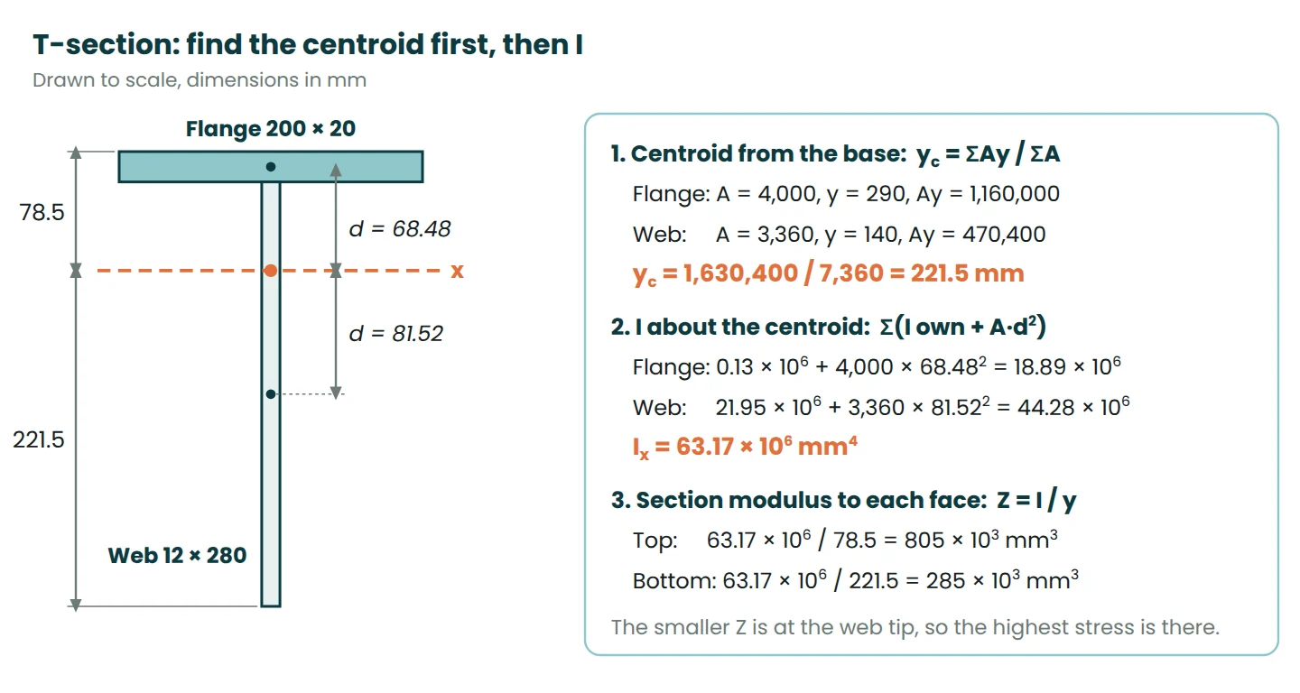
Check: I about the bottom of the web is 424.34 × 10⁶ mm⁴; subtract A·ȳ² = 7,360 × 221.52² = 361.17 × 10⁶ and you get 63.17 × 10⁶ mm⁴ again.
Under a 50 kN·m sagging moment the top of the flange sees 62 MPa compression and the web tip 175 MPa tension, because the tip is nearly three times further from the neutral axis. The smaller Z gives the critical stress.
Section modulus and radius of gyration
Section modulus Z = I / ymax, in mm³, turns the stress formula into σ = M / Z. For a rectangle Z = bh²/6; for a solid circle, πD³/32.
Check the letters in any table. AS 4100 and older British practice use Z for the elastic modulus and S for the plastic modulus. American texts swap them, and Eurocode 3 uses Wel and Wpl. The plastic modulus is the larger: 1.5 times the elastic value for a rectangle.
Radius of gyration r = √(I / A), in mm, is the distance at which you could gather all the area and get the same I. Column slenderness is effective length divided by r. The I-section has rx = 165.9 mm and ry = 46.0 mm.
Why an I-beam is efficient
Bending stress grows linearly with distance from the neutral axis, so material near the axis does little. An I-section puts most of its area in the flanges, as far out as possible, with a thin web to hold them apart and carry shear.
| Section (all 10,080 mm²) | Size (mm) | Ix (10⁶ mm⁴) | Zx (10³ mm³) | Iy (10⁶ mm⁴) |
|---|---|---|---|---|
| I-section (Example 3) | 200 × 400 | 277.6 | 1,388 | 21.36 |
| Plate on edge | 25.2 × 400 | 134.4 | 672 | 0.53 |
| Rectangle, 1 : 2 | 71.0 × 142.0 | 16.9 | 239 | 4.23 |
| Square bar | 100.4 × 100.4 | 8.47 | 169 | 8.47 |
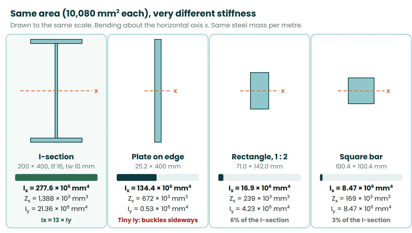
All four weigh the same per metre. The I-section has twice the I of a plate of the same depth, 16 times that of a 1 : 2 rectangle and 33 times that of a square bar. Z gains less (2.1, 5.8 and 8.2 times) because the I-section’s I is divided by a larger distance to its extreme fibre. The plate looks good about x, but its Iy is tiny, so unless it is braced it buckles sideways first.
There is a limit: flanges and webs that are too thin buckle locally before the steel yields, which is why AS 4100 classifies plate elements as compact, non-compact or slender.
Ix vs Iy: the weak axis
Every section has a strong and a weak axis. For the I-section, Ix = 277.6 × 10⁶ mm⁴ but Iy = 21.4 × 10⁶ mm⁴, 13 times smaller. A member fails the easiest way it can, so the weak axis often governs.
Columns buckle about the weak axis
The Euler buckling load of a pin-ended column is P = π²EI / L². Use the I-section as a 4 m column with E = 200 GPa. About x, P is 34,200 kN and L/r = 24. About y, P is 2,640 kN and L/r = 87, so it buckles sideways. Brace it at mid-height in the weak direction and the buckling length about y halves, which raises that load four times, to about 10,500 kN. Euler loads are elastic upper limits. Design to AS 4100 reduces the capacity for yield, imperfections and residual stress, but it still works from the same L/r.
Beams can buckle sideways too
A beam bent about its strong axis has one flange in compression, and that flange behaves like a column. If nothing holds it sideways, the beam kicks out and twists: lateral torsional buckling. Resistance depends on EIy, the section’s torsional stiffness and the distance between lateral restraints. A slab fixed to the top flange usually prevents it; long unbraced beams during erection are where it shows up.
The steel flat bar in our lab report worked example shows the effect: laid flat, its 25.04 × 6.02 mm section has I = 455 mm⁴; on edge, 7,876 mm⁴, about 17 times stiffer.
Formula summary table
| Section | Area A | I about centroidal x | Z = I / ymax | r = √(I/A) |
|---|---|---|---|---|
| Rectangle b × h | bh | bh³ / 12 | bh² / 6 | 0.289h |
| Rectangle, about base | bh | bh³ / 3 | n/a | 0.577h |
| Triangle, base b, height h | bh / 2 | bh³ / 36 | bh²/24 (apex side), bh²/12 (base side) | 0.236h |
| Solid circle, diameter D | πD² / 4 | πD⁴ / 64 | πD³ / 32 | D / 4 |
| Tube, D outside, d inside | π(D² − d²) / 4 | π(D⁴ − d⁴) / 64 | π(D⁴ − d⁴) / (32D) | √(D² + d²) / 4 |
| Box, B × H outside, b × h inside | BH − bh | (BH³ − bh³) / 12 | (BH³ − bh³) / (6H) | √(I / A) |
Common mistakes
- Wrong axis. Swap b and h for the 300 × 600 beam and you get 1.35 × 10⁹ instead of 5.4 × 10⁹ mm⁴, out by four.
- Forgetting A·d². The T-section comes out at 22.1 × 10⁶ mm⁴ instead of 63.17 × 10⁶, 65% low. The I-section is low by a factor of 6.7.
- Shifting a value that isn’t centroidal. Start from bh³/12, not bh³/3, before you add A·d².
- Mixing mm and m. 30,000 MPa × 0.0054 m⁴ = 162, but in MPa·m⁴, which is 162,000 kN·m². Type 162 where kN·m² is wanted and the 6.6 mm deflection becomes 6.6 m. Convert to N and mm, or kN and m, before multiplying; the engineering unit converter handles kN·m to N·mm.
- h² instead of h³. bh²/12 is in mm³, so it cannot be a second moment of area. Likewise, the radius in πD⁴/64 gives one sixteenth of the answer.
- Rounding too early on thin walls. D⁴ − d⁴ subtracts two big, similar numbers. Round the tube’s bore to 102 mm and I comes out 2% high.
After a hand calculation, check it in the section properties calculator. It covers rectangles, boxes, I, T, channel and angle shapes, rounds and tubes, and reports the centroid, Ix, Iy, Z for each face, r and the plastic modulus.
Frequently asked questions
What is the moment of inertia of a rectangle?
It is bh³/12 about the horizontal axis through the centroid, where b is the width and h the depth. About the base it is bh³/3, and about the vertical centroidal axis it is hb³/12.
Why is moment of inertia measured in mm⁴?
Because it adds up area (mm²) times distance squared (mm²). Section modulus divides by a length (mm³), and radius of gyration is √(I/A), in mm.
Is the second moment of area the same as the moment of inertia?
In structural engineering, yes: the moment of inertia of a section means its second moment of area, I, in mm⁴. In dynamics the same name means mass moment of inertia, in kg·m², which is a different quantity.
Why doesn’t my hand calculation match the steel section tables?
Because real sections are not perfect rectangles. Hot-rolled I-sections have root radii where web meets flange, which three rectangles miss, so hand results come out slightly low. Hollow sections have rounded corners, so the table value is slightly below the sharp-corner formula. Design with the published value.
References
- Baker, D., et al. Engineering Statics: Open and Interactive, Chapter 10, Moments of Inertia. Colorado State University. https://engineeringstatics.org/Chapter_10.html
- Baker, D., et al. Engineering Statics: Open and Interactive, Section 10.3, Parallel Axis Theorem. https://engineeringstatics.org/parallel-axis-theorem-section.html
- American Wood Council. (2007). Beam design formulas with shear and moment diagrams (Design Aid No. 6). https://awc.org/wp-content/uploads/2021/12/AWC-DA6-BeamFormulas-0710.pdf
- Hibbeler, R. C. Mechanics of Materials (SI edition). Pearson. Chapters on bending and on geometric properties of an area.
- Gere, J. M., & Goodno, B. J. Mechanics of Materials. Cengage Learning.
- Standards Australia. AS 4100, Steel structures.
- Standards Australia. AS 3600, Concrete structures.
This article is general information for learning and planning. Always follow your project specification, the current standard and the advice of the responsible engineer. For coursework, check your course notes for the notation and sign conventions your lecturer expects.


Leave a Reply