
Bridge pier protection is everything that stops a ship from knocking down a bridge: the fenders, dolphins and islands around the piers, the rules for ships passing under, and the systems that clear traffic off the deck. The practical answer is that you rarely try to make the pier strong enough to win. You keep the ship from reaching it, and you make sure nobody is on the bridge if it does.
The reason is energy. A loaded ship at walking pace carries tens to hundreds of megajoules, while a standard bridge fender is designed for about 0.05 MJ. This guide explains each protection type, how designers choose using the AASHTO vessel collision method, and what changed at real bridges after ships brought them down. For the causes behind these accidents, read why ships hit bridges. The worked example mixes US and SI units, as the design literature does, so keep the free engineering unit converter open for knots, kip-ft and kips.
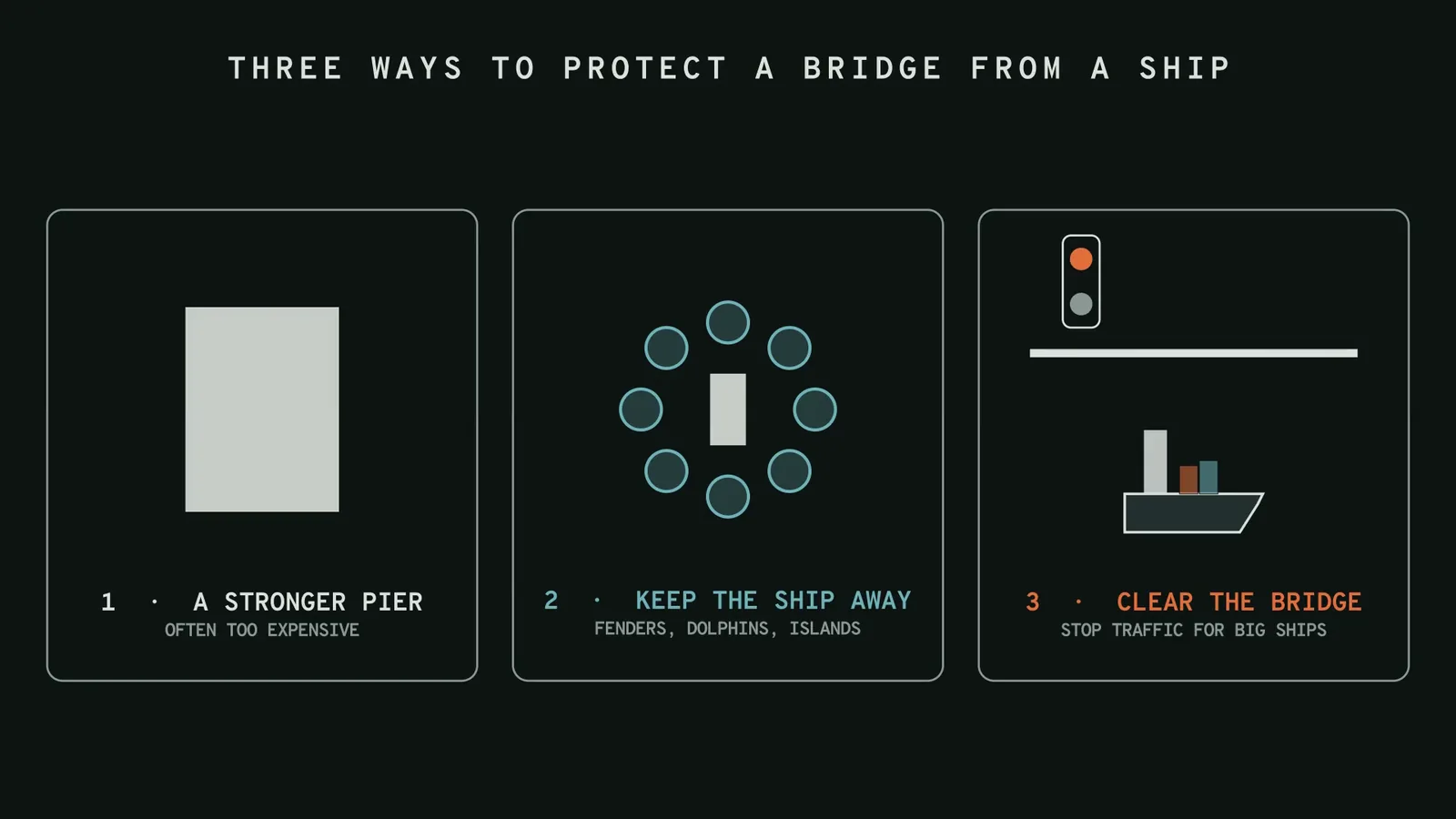
The three strategies for bridge pier protection
- Make the pier strong enough. Design the pier and foundation for the impact force. This works for barges and small ships, but a large ship can impose well over 100 MN, and the pier, piles and footing grow to a size that is often uneconomic.
- Keep the ship away from the pier. Fenders, dolphins, islands and floating barriers absorb the energy or turn the ship before it touches the structure. Wider spans and piers outside the channel do the same job through geometry.
- Keep people off the bridge. If a ship is out of control, stop the traffic. This does not save the bridge, but it saves lives when the other two measures fail.
How each protection type absorbs or deflects energy
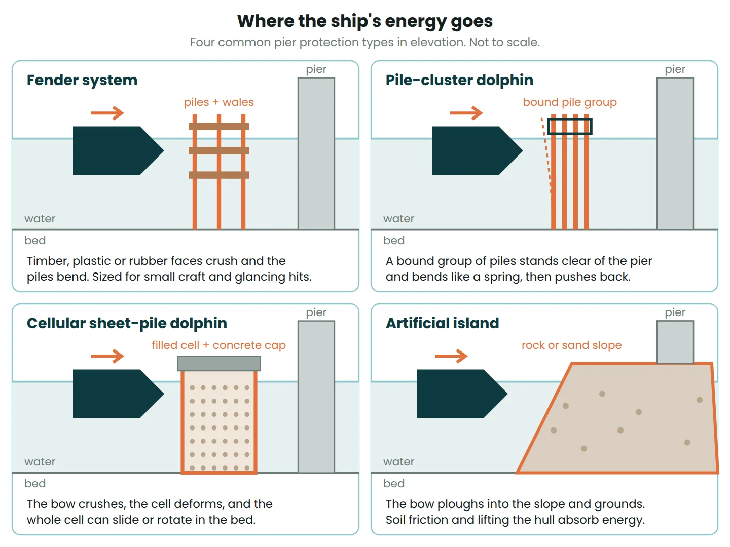
A collision ends only when the ship’s kinetic energy has gone somewhere: into crushing the bow, bending piles, sliding a structure through the seabed, lifting the hull up a slope or stretching a cable. A protection system decides where that energy goes, so that the pier never sees it.
Timber, plastic and rubber fender systems
A fender system is a wall of horizontal wales on vertical piles, built along the channel edge or around the pier. Timber and plastic wales crush and the piles bend; rubber units compress. Fenders are cheap and they guide ships through the span, but their capacity is small. The Florida DOT standard fender system (Design Standards Index 21930) is rated at 38 kip-ft, about 51 kJ. They suit small craft, drifting barges and glancing blows, and every scrape damages them.
Pile-cluster dolphins
A pile-cluster dolphin is a group of timber, steel or concrete piles driven close together and bound at the top. It stands clear of the pier and acts as a spring: the piles bend as cantilevers from the seabed, absorb energy, then push back. Capacity depends on pile size, embedment and how far the group can deflect before it reaches the pier.
Cellular sheet-pile dolphins
A cellular dolphin is a circle of interlocking steel sheet piles filled with sand, rock or tremie concrete and topped with a concrete cap. When a bow hits it, the bow crushes, the cell deforms, and the whole cell can rotate or slide in the seabed. The original Key Bridge in Baltimore had dolphins of this type beside its main piers: 25 ft (7.6 m) sheet-pile cells filled with tremie concrete.
Concrete dolphins
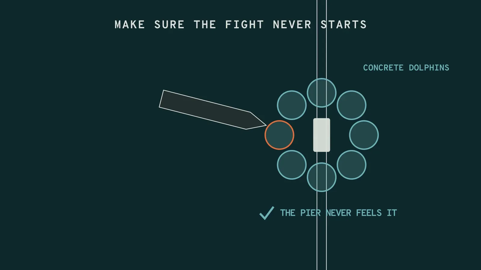
Large concrete dolphins are massive rock-filled cylinders founded deep in the bed, placed in a ring or line so that a ship heading for the pier hits a dolphin first. Most of the energy goes into crushing the ship’s bow, so the dolphin must be stiff, heavy and far enough from the pier that the bow’s overhang cannot reach past it.
Artificial islands
An island is a mound of rock or sand around the pier with sloping sides. A ship that hits it runs aground: the bow ploughs into the slope, the hull lifts, and soil resistance uses up the energy over a long distance. Islands can stop the largest ships, but their footprint grows quickly with water depth, they narrow the waterway and they can change currents and scour. Model tests for the Great Belt bridge in Denmark were used to predict how far a ship would penetrate an island, or whether the slope would deflect it.
Floating barriers and nets
Where water is too deep for islands, anchored pontoons can absorb energy through their mooring lines, and cable nets can catch the bow and stretch to stop it. The AASHTO guide notes that cable systems depend on the shape of the bow to capture it. Moorings, cables and trapped debris make these systems maintenance-heavy.
Strengthening the pier
The AASHTO ship impact formula gives an equivalent static force of P = 8.15 × V × √DWT (kips, with V in ft/s and DWT in tonnes), roughly P ≈ 0.12 × V × √DWT in MN with V in m/s. For the I-10 Mississippi River bridge, a 100,000 DWT ship at 14.7 ft/s (4.5 m/s) gave a head-on design force of 37,800 kips, about 168 MN. AASHTO checks the full force parallel to the channel and, as a separate case, half of it at right angles. Forces like that are why strengthening alone is usually kept for barges and small vessels.
Comparing bridge pier protection systems
Energy and cost levels are relative, because real capacity depends on the design vessel, water depth and soil.
| Protection type | Energy capacity | Space needed | Cost level | Maintenance | Typical use |
|---|---|---|---|---|---|
| Timber or plastic fender | Low (tens of kJ) | Little | Low | High: broken wales, decay | Small craft, barges, guiding ships |
| Rubber fender units | Low to medium | Little | Low to medium | Medium: ageing, fixings | Regular small-vessel contact |
| Pile-cluster dolphin | Low to medium | Small, clear of pier | Low to medium | Medium: pile decay | Barges, smaller ships |
| Cellular sheet-pile dolphin | Medium to high | Several large cells | Medium to high | Low to medium: corrosion | Ships in confined channels |
| Concrete dolphin | High | Large, several per pier | High | Low | Large ships, major crossings |
| Artificial island | Very high | Very large, shallow water | High, rising fast with depth | Low: scour, armour | Main piers of major crossings |
| Floating barrier or net | Medium | Large area plus anchors | Medium to high | High: moorings, debris | Deep water |
| Pier strengthening | Set by design force | None outside pier | High for large ships | Low | Barges, small vessels |
Worked example: ship energy versus fender capacity
The AASHTO kinetic energy expression in US units is KE = CH × W × V² ÷ 29.2 (kip-ft, W in tonnes, V in ft/s). In SI it becomes KE = 500 × CH × M × V² in joules, with M in tonnes and V in m/s. CH is the hydrodynamic mass coefficient, which allows for water moving with the hull: 1.05 where the underkeel clearance is at least half the draft, and 1.25 where it is a tenth of the draft or less. The ship below is illustrative.
- Ship: displacement M = 30,000 t, speed V = 2.5 m/s (about 4.9 knots), deep water so CH = 1.05.
- Energy:
KE = 500 × 1.05 × 30,000 × 2.5² = 98,437,500 J ≈ 98 MJ. - Standard fender: 38 kip-ft × 1.356 kJ per kip-ft ≈ 51.5 kJ. Ratio: 98,400 ÷ 51.5 ≈ 1,900.
- High-capacity fender: one composite fender maker classes systems above 400 kip-ft (about 542 kJ) as high-capacity. Ratio: 98,400 ÷ 542 ≈ 180.
- Drifting at 0.5 m/s (about 1 knot, a dead ship in a current):
KE = 500 × 1.05 × 30,000 × 0.5² ≈ 3.9 MJ, still about 76 times the standard fender and 7 times the high-capacity one. - Stopping distance: if a protective structure resisted with a steady 20 MN (an assumed value), it would need
d = KE ÷ F = 98.4 ÷ 20 ≈ 4.9 mof crush and movement. A fender wall cannot give that; an island, or a massive dolphin plus a crushed bow, can.
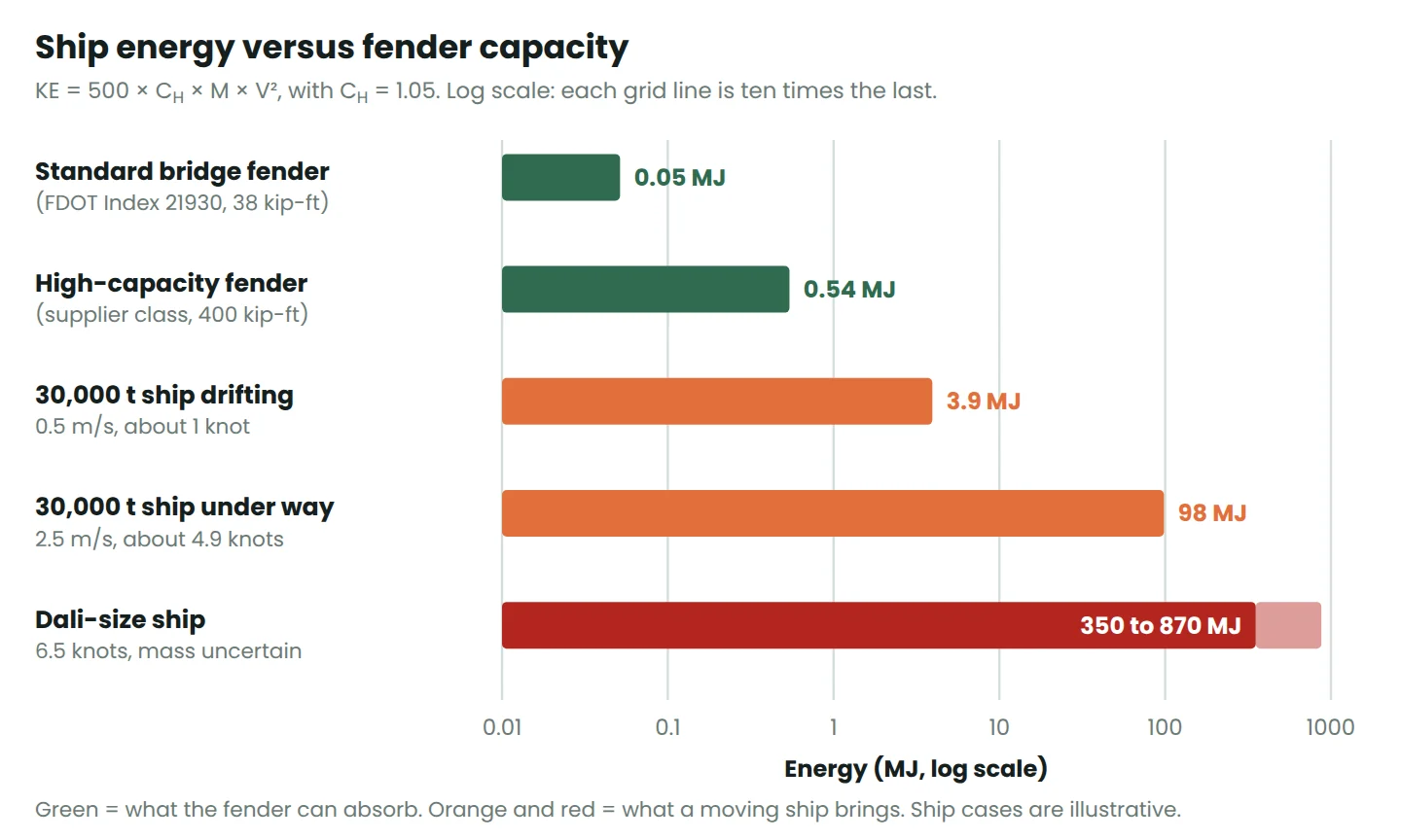
Speed matters more than mass because V is squared: halving the speed cuts the energy to a quarter. For scale, the container ship that hit the Key Bridge in 2024 was moving at about 6.5 knots (3.3 m/s). For any realistic loaded displacement of a ship that size, the formula gives several hundred megajoules.
How designers choose: the AASHTO vessel collision approach
The method comes from the AASHTO Guide Specification and Commentary for Vessel Collision Design of Highway Bridges, first published in 1991 after the Sunshine Skyway collapse and revised in 2009, and from the vessel collision provisions of the AASHTO LRFD Bridge Design Specifications. The steps are:
- Collect vessel traffic data: ships and barges by size, type, loading and draft, plus channel geometry, currents and wind.
- Set the impact speed: the typical transit speed, reducing with distance from the channel centreline, with the yearly mean current as the minimum.
- Classify the bridge: critical or essential bridges are those the owner needs working after an emergency; the rest are typical bridges.
- Calculate the annual frequency of collapse:
AF = N × PA × PG × PC × PF, summed for every vessel group and every exposed pier. Method II, the probability method, is the normal requirement. Method I is a simpler design-vessel approach, and Method III is a cost-effectiveness check for special cases. - Compare with the limit: AF ≤ 0.0001 per year (about 1 in 10,000 years) for critical bridges and AF ≤ 0.001 per year for typical bridges.
- Reduce the risk until it passes: move or strengthen piers, add protection or change operations, then recalculate.
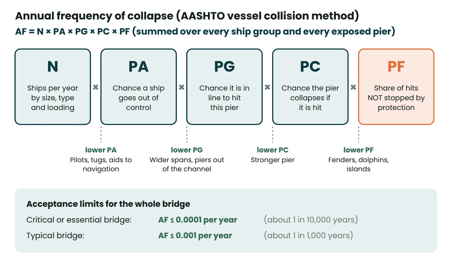
The design vessel is the ship used to size the impact force on a particular pier. Piers can have different design vessels, because a pier at the channel edge sees bigger, faster ships than one in shallow water. AASHTO LRFD also sets a minimum for piers in navigable water: an empty hopper barge (35 ft × 195 ft, about 200 tons) drifting at the yearly mean current. Take design values from the current edition and the owner’s criteria, not from a summary like this one.
Navigation measures and bridge traffic-stop systems
- Wider spans: a longer main span moves the piers away from the sailing line, which lowers PG.
- Channel alignment: a straight approach square to the bridge, with currents along the channel rather than across it. AASHTO raises the aberrancy rate for bridges on bends and for cross-currents.
- Pilots and tugs: a local pilot on board and tugs alongside can hold a ship that loses power or steering.
- Aids to navigation: buoys, leading lights, span lights, radar, port control and live current and wind data.
- Traffic-stop systems: the 1991 AASHTO guide describes motorist warning systems in three parts: hazard detection, verification, and traffic control signals or gates. Some bridges stop traffic for every large ship; others close on an alarm or a distress call.
Real examples of bridge pier protection
Sunshine Skyway, Florida
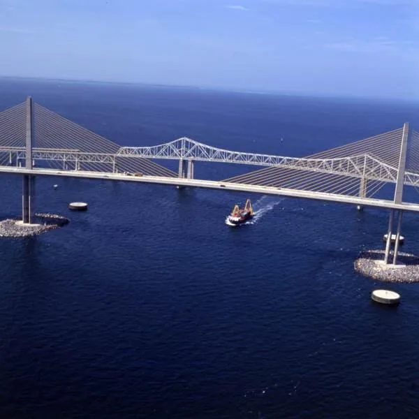
On 9 May 1980 the freighter Summit Venture hit a support pier of the old Sunshine Skyway in a sudden storm. More than 370 m of bridge fell and 35 people died. The replacement, opened in April 1987, has a 366 m main span (the old shipping opening was 263 m) and heavy protection: 36 concrete dolphins, each about 20 m across, beside the piers either side of the main span, and rock islands about 137 m by 101 m around each pylon. A ship should run aground or hit a dolphin long before it reaches a pier.
Tasman Bridge, Hobart, after 1975
On 5 January 1975 the bulk carrier Lake Illawarra, off course in a strong current, hit pier 19 with its bow and then pier 18 along its side. Three spans and 127 m of roadway fell, seven crew and five motorists died, and the bridge did not reopen until October 1977. Only the pile caps of the main navigation span had impact-absorbing fendering.
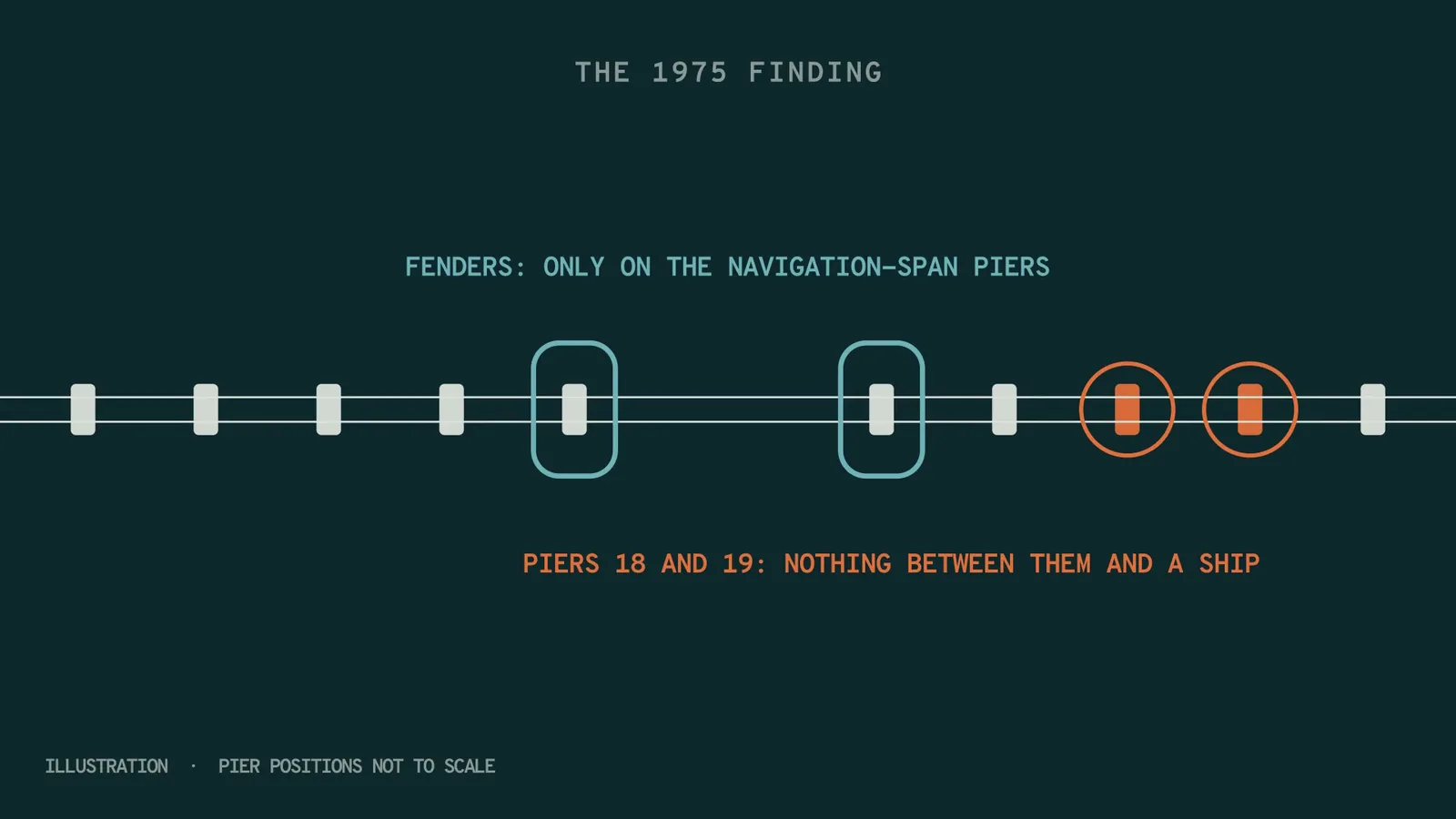
The changes were mostly operational. According to the port authority TasPorts, the bridge now closes to all vehicles three minutes before any ship transit, a licensed pilot is required for vessels over 35 m, a pilot vessel stands by and tugs are ready to assist. Vessels over 25 m may only use the main navigation span with permission. Sensors for current, tide height and wind speed were added, and the Bowen Bridge upstream, completed in 1984, gave the city a second crossing.
Francis Scott Key Bridge replacement, Baltimore
The NTSB found that the original Key Bridge was almost 30 times above the AASHTO acceptable risk threshold for a critical bridge, and asked the owners of 68 other older bridges to run the assessment. The full story is in our article on Key Bridge collapse engineering lessons. The replacement is a cable-stayed bridge with a 1,665 ft (507 m) main span and 230 ft (70 m) clearance. Each pylon is ringed by a pile-supported concrete fender about 23 ft (7 m) thick and larger than a football field, designed so that neither the bow above water nor the bulbous bow below it can touch the pier. The Maryland Transportation Authority’s updated estimate of US$4.3 to 5.2 billion names pier protection as a major cost driver, with opening expected in late 2030.
Great Belt East Bridge, Denmark
The East Bridge, opened to road traffic in 1998, is a suspension bridge with a 1,624 m main span and 65 m clearance over a major shipping route into the Baltic. Its five most exposed piers and its anchor blocks are protected by artificial islands, sized from ship collision studies and model tests of ships striking island slopes.
Common mistakes in bridge pier protection
- Protecting only the navigation span. Ships out of control do not stay in the channel. The Tasman Bridge was hit on unprotected side piers.
- Treating fenders as ship stoppers. A fender is a guide and a bumper. Check its rated energy against the design vessel.
- Designing for yesterday’s ships. Bridges serve for 75 years or more and ships keep getting larger. Re-run the risk calculation when traffic changes.
- Forgetting the shape of the bow. A raked bow can reach over a low dolphin, and a bulbous bow reaches forward under water. Protection must stop both.
- Placing protection too close. A dolphin that deflects 3 m cannot sit 2 m from the pier. Allow for deflection, sliding and bow overhang.
- Ignoring scour and upkeep. Islands and dolphins change local currents, and fenders that are not repaired after each hit quietly lose capacity.
- Leaving people on the bridge. A traffic stop costs little and still works when every structural measure fails.
Frequently asked questions
What is a dolphin in bridge engineering?
A dolphin is a free-standing structure in the water, separate from the bridge, that a ship hits instead of the pier. It can be a bound cluster of piles, a filled sheet-pile cell or a large concrete cylinder.
Why don’t engineers just make bridge piers stronger?
Because head-on forces from large ships can exceed 100 MN, and designing every exposed pier and foundation for that usually costs far more than keeping ships away. Strengthening is used for barges and small vessels.
How much energy can a bridge fender absorb?
Typically tens to hundreds of kilojoules. The Florida DOT standard fender is rated at 38 kip-ft (about 51 kJ), while a moving ship can carry tens or hundreds of megajoules. If you are comparing US catalogue ratings, the engineering unit converter turns kip-ft into kJ.
Did the Key Bridge have pier protection?
Yes, but not enough for the ships using the port in 2024. Its main piers had concrete-filled sheet-pile dolphins, yet the Dali struck pier 17 directly, and no vulnerability assessment had been done to show the risk.
References
- AASHTO. Guide Specification and Commentary for Vessel Collision Design of Highway Bridges (1991; 2nd edition 2009).
- National Transportation Safety Board (2025). NTSB Recommends 68 Bridges in US be Evaluated for Risk of Collapse from Vessel Strike.
- Maryland Transportation Authority (2025). Updated estimates for the Key Bridge rebuild.
- TasPorts (2025). 50th anniversary: Hobart’s Tasman Bridge disaster.
- Florida Department of Transportation. Design Standards Index 21930: Fender System.
- Louisiana Transportation Research Center. Replacement of Fender System at I-10 Mississippi River Bridge.
- Technical University of Denmark. Ship impact against protection islands.
This article is general information for learning and planning. Always follow your project specification, the current standard and the advice of the responsible engineer.


Leave a Reply