
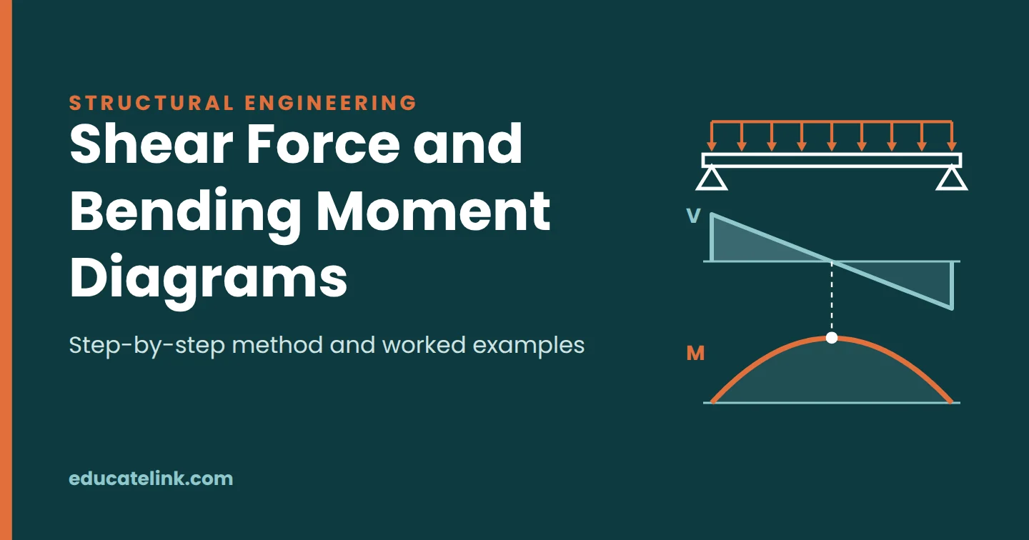
Shear force and bending moment diagrams show how the internal shear force (V) and bending moment (M) change along a beam. To draw them, find the support reactions from equilibrium, cut the beam at a few sections, write V and M from the forces on one side of each cut, then plot both graphs under the beam. Within a span, the largest bending moment sits where the shear force passes through zero. For a simply supported beam that gives the two results every engineer remembers: PL/4 under a central point load and wL²/8 under a full uniformly distributed load (UDL).
Five beams are worked below, from the simple cases to a part-loaded span, a cantilever and an overhang. Every number was checked by calculation and every diagram is drawn from those numbers.
You can check any of these beams with the free beam calculator. It uses the same sign convention as this article, so its reactions, shear forces and moments match the worked examples.
What shear force and bending moment are
Imagine sawing through a loaded beam at section X–X. Each piece would drop and rotate unless the material across the cut held it. That material supplies two internal actions:
- Shear force V: the internal vertical force, equal to the sum of the vertical forces on one side of the cut.
- Bending moment M: the internal couple, equal to the sum of the moments of those forces about the cut.
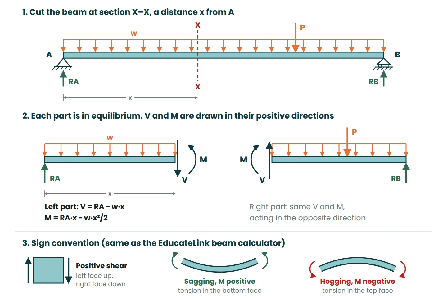
In the figure, the left part carries RA and a length x of the UDL, so equilibrium gives V = RA − w·x and M = RA·x − w·x²/2. The right part, with P and RB, gives the same V and M acting the opposite way. Use whichever side has fewer loads.
Shear tries to slide one part past the other. Moment curves the beam, putting one face in tension and the other in compression. Those are the two effects you design the member for.
Sign convention: sagging moment is positive
This article and the calculator use the usual textbook convention:
- Positive shear: the net force to the left of the section acts upwards. Working from the left end, V is the upward forces minus the downward forces so far.
- Positive moment (sagging): the beam bends concave upwards, with tension in the bottom face. Hogging is negative, with tension in the top face.
- Positions are measured from the left end, and loads are positive downwards.
The sign carries information. Sagging means tension at the bottom, so a concrete beam needs bottom bars; hogging means top bars. Switch convention halfway through and a step in the shear diagram goes the wrong way, the moment fails to close at the far support, and steel can end up on the wrong face.
Two variations catch people out. Many concrete designers draw the moment diagram on the tension side, which puts sagging below the line; the values do not change. (Here, positive values are plotted above the line.) And the shear sign depends on which way the beam faces. The calculator fixes a cantilever at the left end, so its shear is positive; mirror the beam and the shear turns negative with the same size.
How to draw shear force and bending moment diagrams, step by step
- Sketch the beam with all loads, supports and dimensions. For the reactions only, replace each UDL with its resultant (w × loaded length) at the middle of the loaded length.
- Take moments about one support to find the other reaction, then use ΣFy = 0. Check with moments about the second support.
- Mark the key points: supports, point loads, the ends of each UDL and any free end. Between key points, V and M each follow one equation.
- Cut each segment at a distance x and write V(x) and M(x) from the forces on one side. Only the part of a UDL on that side counts.
- Work out V and M at each key point. At a point load or support, record V just left and just right, as it has two values there.
- Plot the shear force diagram under the beam and the bending moment diagram under that, lined up.
- Find the maximum moment where V = 0 or changes sign: solve V(x) = 0 and substitute x into M(x). Check the supports too.
- Check: M is zero at end pins, end rollers and free ends, and the area of the shear diagram between two points equals the change in moment.
Load, shear and moment relationships
Equilibrium of a short slice of beam gives three rules (derived in Engineering Statics, chapter 8):
dV/dx = −w: the slope of the shear diagram equals the load intensity, negative for downward load. A 10 kN/m UDL makes V fall 10 kN per metre.dM/dx = V: the slope of the moment diagram equals the shear. Where V = 0 the moment curve is flat, so that is where the peak sits.M₂ − M₁ = area under the shear diagram from x₁ to x₂: areas above the line add moment, areas below subtract it.
| Load on the segment | Shear force diagram | Bending moment diagram |
|---|---|---|
| No load | Horizontal line | Straight line (horizontal where V = 0) |
| Point load P | Vertical step of P, downwards for a downward load | Kink (sudden change of slope); a peak if V changes sign |
| UDL w | Straight line sloping at −w per metre | Parabola |
| Linearly varying load | Parabola | Cubic curve |
| Applied couple | No change | Vertical jump equal to the couple (upwards for a clockwise couple, reading left to right) |
Worked examples
All five use kN and metres, so moments are in kN·m, with x measured from the left end.
Example 1: central point load (PL/4)
A 6 m simply supported beam carries 40 kN at midspan. By symmetry RA = RB = 20 kN. V is +20 kN up to the load, then steps down 40 kN to −20 kN. With no load between A and midspan, M = 20x, a straight line rising to 60 kN·m under the load. In general Mmax = (P/2) × (L/2) = PL/4 = 40 × 6 ÷ 4 = 60 kN·m.
Example 2: full-span UDL (wL²/8)
The same beam carries 10 kN/m over its full length. The total load is 60 kN, so RA = RB = 30 kN. V = 30 − 10x crosses zero at x = 3 m, and M = 30x − 5x² gives M(3) = 90 − 45 = 45 kN·m, which is wL²/8 = 10 × 6² ÷ 8. Check: the shear triangle from 0 to 3 m has area ½ × 30 × 3 = 45.
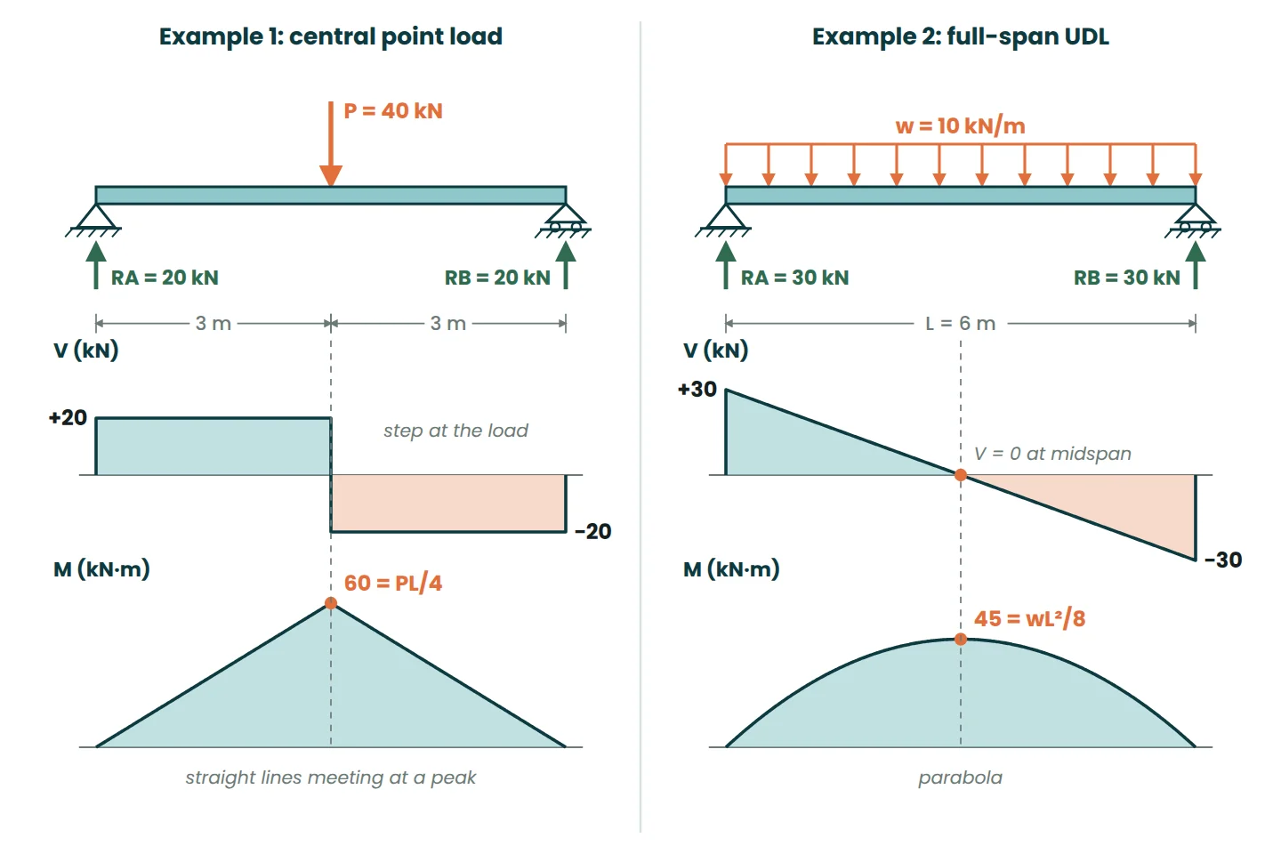
For the same total load W, a central point load gives WL/4 and a UDL gives WL/8, so spreading the load halves the peak. The parabola is also flat near midspan: at the quarter points M is still 33.75 kN·m, 75% of the maximum.
Example 3: off-centre point load plus a partial UDL
An 8 m simply supported beam AB carries 20 kN/m over the first 4 m and a 40 kN point load 6 m from A. The UDL resultant is 80 kN acting 2 m from A.
- Moments about A:
RB × 8 = 80 × 2 + 40 × 6 = 400, so RB = 50 kN. - Vertical equilibrium:
RA = 80 + 40 − 50 = 70 kN. Check about B:RA × 8 = 80 × 6 + 40 × 2 = 560, so 70 kN again. - 0 to 4 m:
V = 70 − 20xandM = 70x − 10x². - 4 to 6 m:
V = −10 kNandM = 160 − 10x, so 120 kN·m at 4 m and 100 kN·m at 6 m. - 6 to 8 m:
V = −50 kNand, from the right,M = 50 × (8 − x).
V crosses zero inside the UDL: 70 − 20x = 0 gives x = 3.5 m, and Mmax = 70 × 3.5 − 10 × 3.5² = 122.5 kN·m. Check with areas: the positive shear triangle is ½ × 70 × 3.5 = 122.5 and the negative areas after it total 2.5 + 20 + 100 = 122.5, so M closes to zero at B.
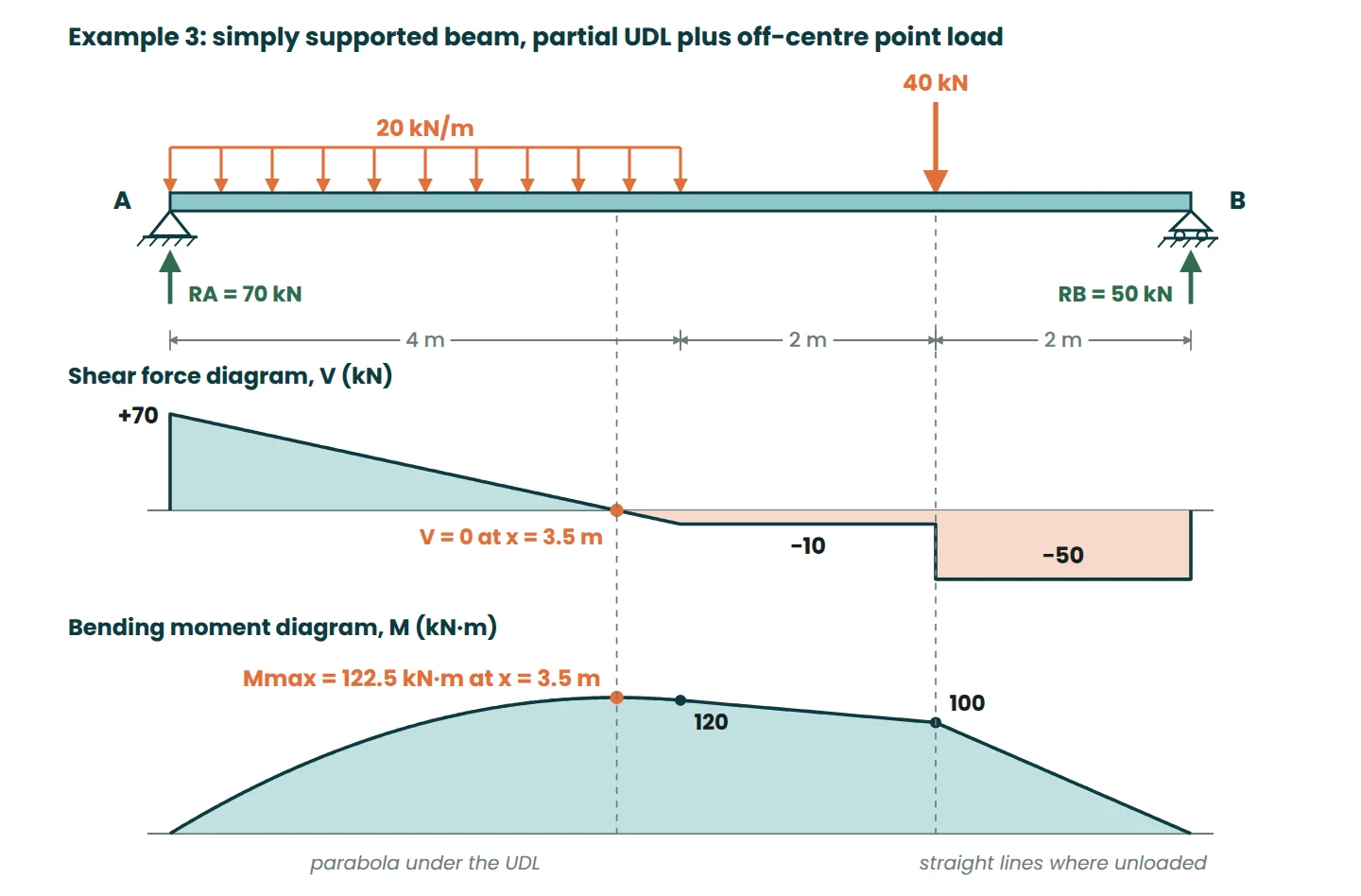
The maximum is neither under the point load nor at midspan. Here the midspan value (120 kN·m) happens to be close, but that is luck. Always find where V = 0.
Example 4: cantilever with a UDL and a tip load
A 3 m cantilever is fixed at A, on the left, and carries 8 kN/m over its length plus 20 kN at the free end B.
- Vertical reaction:
RA = 8 × 3 + 20 = 44 kNupwards. - The loads have a moment about A of
24 × 1.5 + 20 × 3 = 96 kN·m, so the wall supplies 96 kN·m anticlockwise and the internal moment at A is −96 kN·m (hogging).
From the free end there is no reaction to carry. At a distance u from B, V = 20 + 8u and M = −(20u + 4u²): at the wall V = 44 kN and M = −96 kN·m, and at midlength M = −39 kN·m. V never reaches zero, so the peak moment is at the support. The V = 0 rule finds peaks within a span; supports must be checked separately.
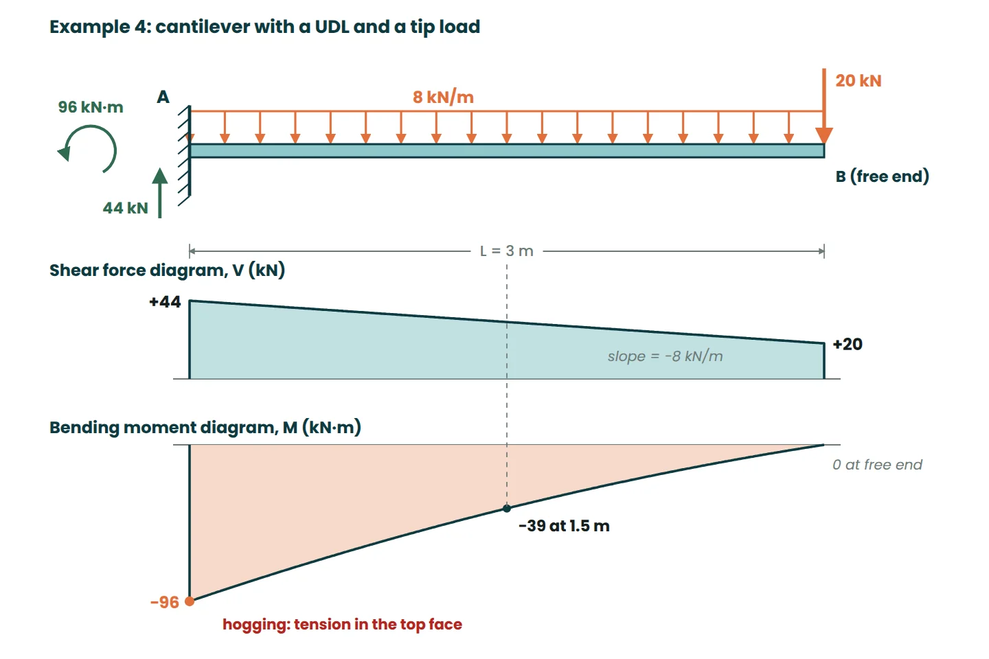
The whole cantilever hogs, so the tension is in the top face: a concrete cantilever has its main bars at the top, anchored well back into the support. The calculator’s moment diagram for this beam starts at −96 kN·m at the wall.
Example 5: overhanging beam and the point of contraflexure
Supports A and B are 6 m apart and the beam overhangs B by 2 m to a free end C. It carries 10 kN/m over the full 8 m and 20 kN at C.
- Moments about A:
RB × 6 = 80 × 4 + 20 × 8 = 480, so RB = 80 kN and RA = 100 − 80 = 20 kN. - Span AB:
V = 20 − 10xis zero at x = 2 m, andM = 20x − 5x²peaks at +20 kN·m. - At B:
M = 20 × 6 − 5 × 6² = −60 kN·m. From C,−(20 × 2 + 20 × 1) = −60 kN·magrees. - Shear at B jumps from −40 to +40 kN (the 80 kN reaction), then falls to +20 kN at C.
Setting 20x − 5x² = 0 gives x = 4 m, the point of contraflexure, where the moment changes from sagging to hogging and the tension moves from the bottom face to the top.
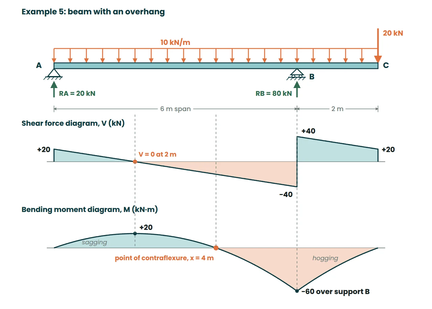
The overhang cuts the span moment from 45 kN·m (Example 2) to 20 kN·m but adds 60 kN·m of hogging over B. Load arrangement matters too: with only the span loaded, the sagging moment returns to 45 kN·m; with only the overhang loaded (its UDL plus the 20 kN), RA becomes −10 kN, so A must hold the beam down. Design for the worst arrangement, not just the full load.
Standard results for common beams
These cover most hand checks. Each was confirmed with the calculator for L = 6 m, P = 40 kN and w = 10 kN/m.
| Beam and load | Reactions | Max shear | Max moment and location |
|---|---|---|---|
| Simply supported, central point load P | P/2 each | P/2 | PL/4 at midspan |
| Simply supported, P at a from A (b = L − a) | RA = Pb/L, RB = Pa/L | Larger reaction | Pab/L under the load |
| Simply supported, two loads P at third points | P each | P | PL/3 between the loads |
| Simply supported, full UDL w | wL/2 each | wL/2 | wL²/8 at midspan |
| Cantilever, point load P at the tip | P | P | −PL at the support |
| Cantilever, full UDL w | wL | wL | −wL²/2 at the support |
| Propped cantilever, full UDL w | 5wL/8 fixed end, 3wL/8 prop | 5wL/8 | −wL²/8 at the fixed end; +9wL²/128 at 3L/8 from the prop |
| Fixed both ends, full UDL w | wL/2 each | wL/2 | −wL²/12 at the supports; +wL²/24 at midspan |
The last two are statically indeterminate: their reactions depend on the deflected shape, not equilibrium alone. That is why wL²/8 must not be used for fixed or continuous beams.
How the diagrams are used in design
Moment governs flexure. The peak moment sizes the section and the flexural reinforcement. For an elastic section, the extreme fibre stress is σ = M × y ÷ I = M ÷ Z. Put Example 3 on a 200 × 400 mm rectangle: Z = bh²/6 = 5.33 × 10⁶ mm³, so σ = 122.5 × 10⁶ N·mm ÷ 5.33 × 10⁶ mm³ = 23.0 MPa, to be compared with the material’s design strength. Moment of inertia of common sections explains I and Z, and the section properties calculator works them out for common shapes.
The sign tells you where the steel goes. Sagging needs bottom bars; hogging over supports, at cantilever roots and on overhangs needs top bars. The point of contraflexure marks where the tension changes face, so it guides where bars can be curtailed. Codes still require bars to extend past their theoretical cut-off and be fully anchored, and since the contraflexure point moves with the load arrangement, detail from the moment envelope of all load cases.
Shear governs stirrups and webs. Shear peaks near the supports, so stirrups are closer there (see stirrup cutting length calculation for spacing zones). In Example 3 the shear is 70 kN at A but only 10 kN between 4 m and 6 m, where minimum shear steel is likely to govern. Many codes, ACI 318 among them, let you design for the shear an effective depth from the support face, provided the reaction compresses the beam end, the load acts on or near the top of the beam and no point load acts within that distance.
Common mistakes
- Assuming the peak is at midspan. For 40 kN at 2 m on a 6 m span, midspan M is 40 kN·m but the true maximum, under the load, is 53.3 kN·m.
- Using the whole UDL when the cut is part-way through it. Only the length on your side counts, acting at its own midpoint.
- Quoting one shear value at a point load or support. Give both sides.
- Mixing sign conventions between textbook, lecture notes and software. Pick one, and remember a mirrored cantilever flips the shear sign.
- Forgetting the fixed-end moment of a cantilever, or drawing it as sagging.
- Using wL²/8 for a fixed, propped or continuous beam. It overstates the span moment and misses the hogging at the supports.
- Unit slips. kN and m give kN·m; a stray millimetre puts you out by 1000.
- Not closing the diagram. If M does not return to zero at an end support or a free end, a reaction or load is wrong.
Running the beam through the beam calculator after a hand calculation catches most of these. For a beam bending experiment write-up, see how to write a lab report.
Frequently asked questions
What is the difference between shear force and bending moment?
Shear force is the internal vertical force at a section of a beam; bending moment is the internal turning effect at that section. Shear tends to slide one part past the other, while moment bends the beam, causing tension on one face and compression on the other.
Where does the maximum bending moment occur?
Within a span, it occurs where the shear force is zero or changes sign, because dM/dx = V. In cantilevers and over interior supports the largest moment is often at a support, so check those as well.
What is a point of contraflexure?
It is a point where the bending moment changes sign between sagging and hogging, so the moment there is zero. It occurs in overhanging, fixed and continuous beams and marks where the main tension steel moves between bottom and top.
Why is the bending moment zero at a simply supported end?
A pin or roller at the end of a beam cannot resist rotation and has no beam beyond it, so nothing can create a moment there. A free end is zero for the same reason. Over an interior support, such as B in Example 5, the moment is not zero.
References
- Baker, D. and Haynes, W. Engineering Statics: Open and Interactive, chapter 8, Internal forces. engineeringstatics.org
- MIT OpenCourseWare. 2.001 Mechanics and Materials I, Fall 2006, lectures 5 and 6: Shear force and bending moment diagrams. ocw.mit.edu
- American Wood Council. Design Aid No. 6: Beam Design Formulas with Shear and Moment Diagrams. awc.org
- Hibbeler, R. C. Mechanics of Materials. Pearson.
- American Concrete Institute. ACI 318-19, Building Code Requirements for Structural Concrete.
- Standards Australia. AS 3600, Concrete structures.
This article is general information for learning and planning. Check your course notes for the sign convention your examiner expects, and for real structures always follow your project specification, the current standard and the advice of the responsible engineer.

Leave a Reply