
This retaining wall stability calculator checks a concrete cantilever wall for overturning, sliding and bearing pressure, per metre run. Enter the wall sizes, backfill properties and surcharge, and it lists every force with its lever arm about the toe.
Earth pressure uses Rankine’s active coefficient with level backfill. The default 4 m wall passes overturning (FS 3.52) and bearing (80.2 kPa) but fails sliding, with FS 1.04 against the 1.5 required.
How to use it
- Enter the geometry in metres, from Overall height H (top of wall to underside of base) to Heel length (behind stem).
- Enter the Backfill unit weight γ, Backfill friction angle φ’ and Surcharge on backfill (kPa).
- Enter the Concrete unit weight and Foundation soil friction angle, which sets base friction.
- Set the Allowable bearing pressure, Required FS overturning and Required FS sliding.
- Read the ticks and crosses under Stability checks.
How the stability checks are calculated
B = toe + stem bottom + heel, stem height h = H − base thickness, and Ka = (1 − sin φ’)/(1 + sin φ’). The stem’s back face is vertical, with the batter on the front. Weights and lever arms about the toe:
- Stem rectangle t1hγc at toe + t2 − t1/2
- Stem batter ½(t2 − t1)hγc at toe + ⅔(t2 − t1)
- Base Btbγc at B/2; soil on heel (heel × h × γ) at B − heel/2
Thrusts act on a vertical plane through the heel: Pa = ½KaγH² at H/3 and Pq = KaqH at H/2. FS overturning = ΣMR/MO, and FS sliding = μΣV/(Pa + Pq) with μ = tan(⅔φbase). The surcharge load is left out of both.
For bearing, V = ΣV + q × heel, x̄ = (moments about the toe − MO)/V and e = B/2 − x̄. If |e| ≤ B/6, q = (V/B)(1 ± 6e/B); otherwise qmax = 2V/(3a), where a is the distance from the resultant to the nearer edge, and qmin = 0. There is no passive resistance, no soil over the toe and no water pressure.
Worked example: 4.0 m cantilever wall
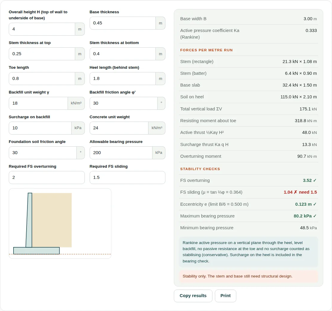
The defaults give B = 0.8 + 0.4 + 1.8 = 3.00 m, h = 4.0 − 0.45 = 3.55 m and Ka = 0.5/1.5 = 0.333.
| Part | W (kN) | x (m) | M (kN·m) |
|---|---|---|---|
| Stem, 0.25 × 3.55 × 24 | 21.3 | 1.075 | 22.9 |
| Batter, 0.5 × 0.15 × 3.55 × 24 | 6.4 | 0.90 | 5.8 |
| Base, 3.00 × 0.45 × 24 | 32.4 | 1.50 | 48.6 |
| Soil, 1.8 × 3.55 × 18 | 115.0 | 2.10 | 241.5 |
| Total | 175.1 | 318.8 |
- Pa = 0.5 × 0.333 × 18 × 4.0² = 48.0 kN; Pq = 0.333 × 10 × 4.0 = 13.3 kN
- MO = 48.0 × 4.0/3 + 13.3 × 2.0 = 90.7 kN·m, so FS overturning = 318.8/90.7 = 3.52
- μ = tan 20° = 0.364; FS sliding = 0.364 × 175.1/61.3 = 1.04, under 1.5
- Adding 18.0 kN of surcharge at 2.10 m: V = 193.1 kN, x̄ = (318.8 + 37.8 − 90.7)/193.1 = 1.377 m and e = 0.123 m, inside B/6 = 0.500 m
- qmax = (193.1/3.00)(1 + 6 × 0.123/3.00) = 80.2 kPa; qmin = 48.5 kPa
Before you rely on the result
- The default wall fails sliding. With everything else unchanged, a 3.0 m heel lifts FS sliding to 1.57. The tool does not model a shear key or passive resistance.
- No water pressure is included, so the backfill must be drained.
- Backfill must be level. A sloping backfill gives more thrust than this Ka.
- This is a stability check only. The stem and base still need structural design.
Questions people ask
What factor of safety is needed against overturning and sliding?
The calculator defaults to 2.0 for overturning and 1.5 for sliding, and you can change both. Use the values in your local code; Eurocode 7 uses partial factors instead.
Why must the eccentricity stay within B/6?
Inside B/6, the middle third of the base, the whole base stays in compression. Beyond it, part of the base lifts off and the tool marks a fail. The default wall has e = 0.123 m against 0.500 m.
How do you calculate active earth pressure on a retaining wall?
For level backfill, Rankine gives Ka = (1 − sin φ’)/(1 + sin φ’), which is 0.333 at 30°. The thrust is ½KaγH² at H/3, plus KaqH at H/2 for a surcharge: 48.0 and 13.3 kN/m for the default wall.
Related tools
- Bearing Capacity: Ultimate and allowable bearing capacity of shallow foundations.
- Concrete Volume: Slabs, footings, columns, beams, walls and stairs in m³ or yd³.
- Rebar Weight: Weight of reinforcing steel in kg, tonnes or lb, metric and US bars.
Results are for estimating, checking and learning. Design work should be checked against the current code and your project specification, and signed off by a qualified engineer. See all 20 engineering calculators.