
Stirrup cutting length is the length of straight bar you cut before bending it into a closed stirrup. The standard formula is L = 2 × (A + B) + 2 × hook − bend deductions, where A and B are the out-to-out sizes of the stirrup: the member size minus twice the clear cover. For a 230 × 230 mm column with 8 mm ties, 40 mm clear cover and 135° hooks, it gives 664 mm.
That is the figure many site bar bending schedules use, and it is what our calculator returns. It is an estimating convention, though. The hook you actually get depends on the pin the bar bender uses, so this page also shows how to check the finished hook against the seismic rules before you cut a whole batch.
To run your own member sizes, use the free bar cutting length calculator. It applies the same convention, so the numbers below will match it.
What a stirrup does
The same bar goes by several names: stirrups or links in beams, ties or lateral ties in columns, and ligatures or fitments in Australia, where AS 3600 calls them fitments. Whatever the name, it does three jobs.
- In beams it carries shear across diagonal cracks, mostly near the supports where shear is highest.
- In columns it stops the main bars buckling outwards under load and confines the concrete core.
- In every member it holds the cage together at the right cover while the concrete goes in.
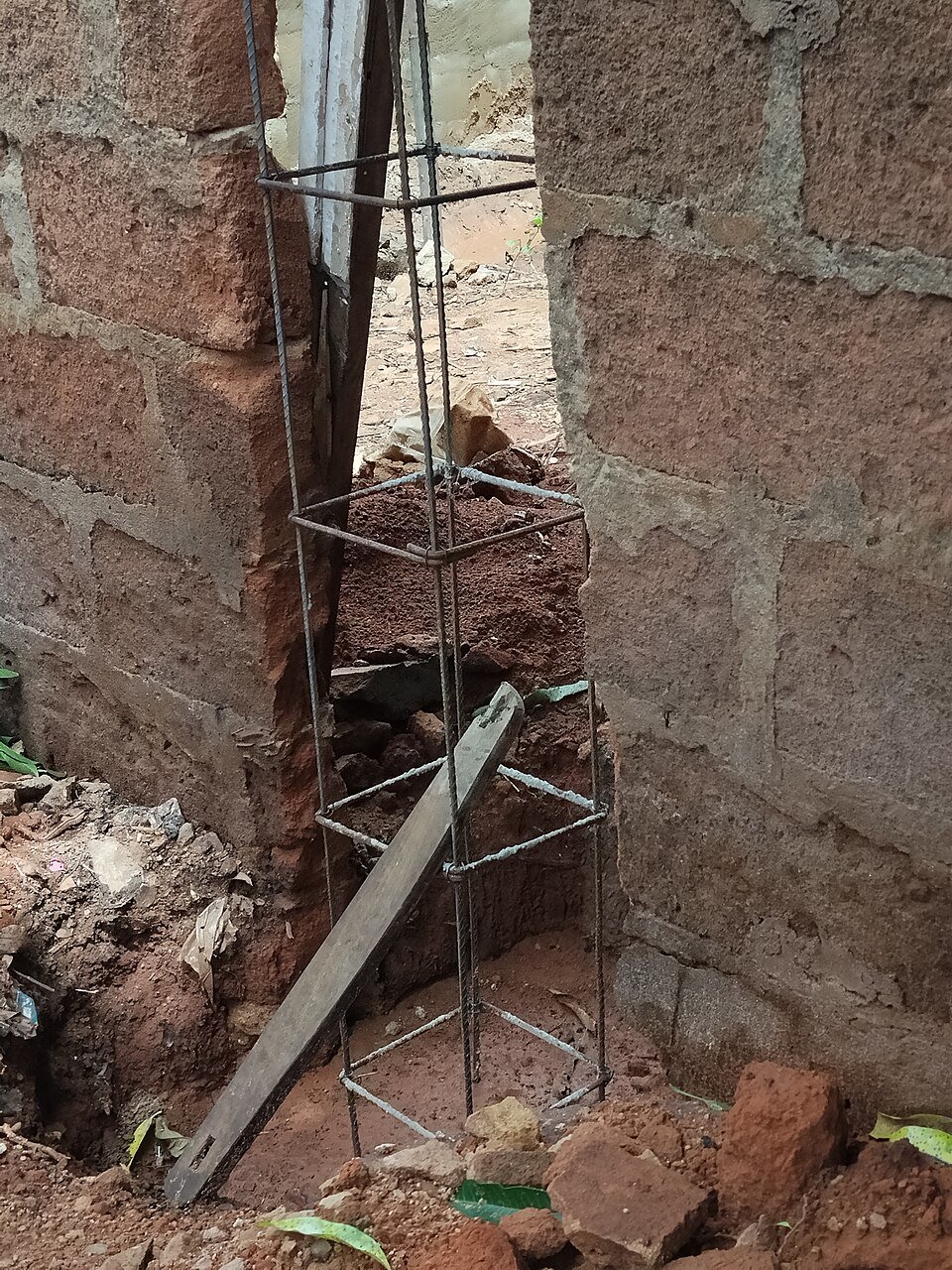
In earthquake-resistant frames, confinement matters most. When the cover concrete spalls, a tie with 90° hooks can spring open because its ends sit in that cover. A 135° hook wraps round a main bar and anchors its tail in the core, so the tie keeps working. That is why ductile detailing codes ask for 135° hooks.
The stirrup cutting length formula, step by step
This is the convention the calculator uses: sizes measured to the outside of the bar (out-to-out), a hook allowance of 10d with a 75 mm minimum, and fixed deductions for each bend, where d is the stirrup bar diameter. In India, bending and fixing practice is covered by IS 2502.
- Take the member size from the drawing: width b and overall depth h.
- Take the clear cover to the outside face of the stirrup.
- Work out the out-to-out sizes:
A = b − 2 × coverandB = h − 2 × cover. - Hook allowance:
10dper hook, but not less than 75 mm. - Bend deductions: 2d for each of the three 90° corners and 3d for each of the two 135° hook bends.
- Add it up:
L = 2 × (A + B) + 2 × hook − 3 × 2d − 2 × 3d.
When 10d governs the hook, the hooks and deductions net out to 8d, so L = 2 × (A + B) + 8d. That shortcut is handy for checking a schedule by eye.
Where the bend deductions come from
Out-to-out sizes run to the sharp outside corner, but the bar goes round each corner on a curve, so adding the sides overstates the bar. For a 90° bend round a pin of 4d internal diameter, the centreline radius is 2.5d and the overstatement is 2 × 3d − π × 2.5d ÷ 2 = 2.07d. The 2d deduction is close to exact. The 3d for a 135° bend comes from the same rule-of-thumb table used in many schedules (1d for 45°, 2d for 90°, 3d for 135°, 4d for 180°), and it is much less exact, as the hook check below shows.
Check which face the cover is measured to
IS 456 applies nominal cover to all steel, links included, and asks for at least 40 mm to the main bars of a column. Cover is normally measured to the outermost bar, which is the stirrup. If a drawing gives 40 mm to the main bars instead, the cover to an 8 mm tie is 32 mm and the stirrup grows to 166 mm out-to-out. Read the general notes before you subtract.
How the codes differ on hooks
The hook is where codes differ most. The rules below all use a 135° bend for closed hoops (ACI 318 allows 90° for circular hoops), but they set different straight extensions after the bend.
| Code | Bend | Minimum straight extension | 8 mm bar | 10 mm bar |
|---|---|---|---|---|
| IS 13920:1993 (superseded) | 135° | 10d, not less than 75 mm | 80 mm | 100 mm |
| IS 13920:2016 with Amendment 1 | 135° | 8d, not less than 75 mm | 75 mm | 80 mm |
| ACI 318 seismic hook | 135° | 6d, not less than 75 mm (3 in.) | 75 mm | 75 mm |
| AS 3600 standard hook | 135° or 180° | 4d, not less than 70 mm | 70 mm | 70 mm |
| EducateLink calculator default | 135° | 10d allowance, not less than 75 mm | 80 mm | 100 mm |
IS 13920:2016 was first printed with 6d and 65 mm. Amendment 1 (2017) raised it to 8d and 75 mm, so check that your copy includes the amendments. The old 10d rule from the 1993 edition is still the common site default, and our calculator uses it. A 10d allowance is at least as long as every minimum in the table, but an allowance in a formula is not the same as the tail you get after bending.
Worked example 1: a 230 × 230 mm column
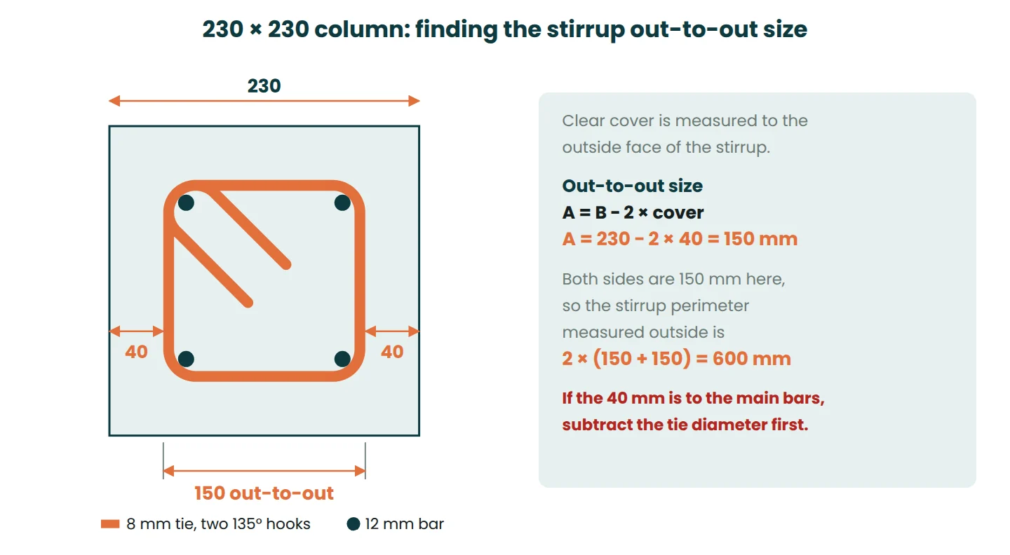
Column 230 × 230 mm, 8 mm ties, 40 mm clear cover to the ties, 135° hooks.
- Out-to-out: A = B = 230 − 2 × 40 = 150 mm.
- Perimeter: 2 × (150 + 150) = 600 mm.
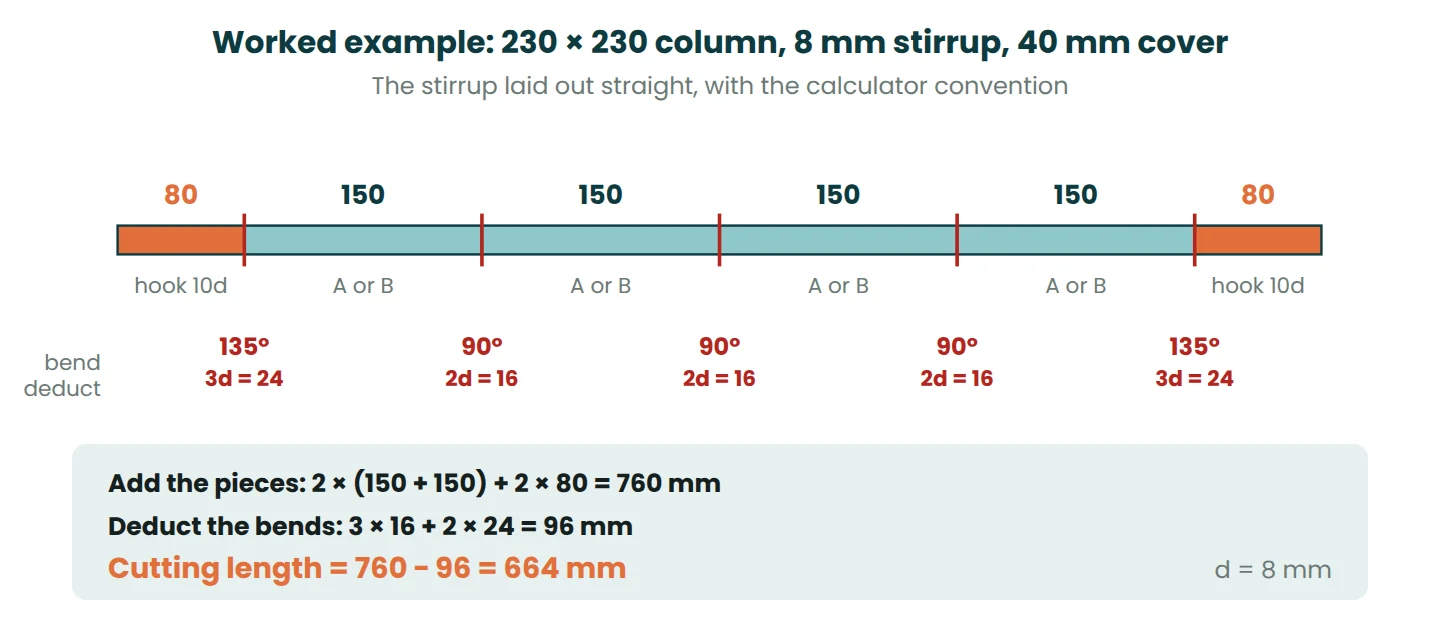
- Hooks: 10 × 8 = 80 mm, which beats the 75 mm minimum, so 2 × 80 = 160 mm.
- Deductions: 3 × 2 × 8 + 2 × 3 × 8 = 48 + 48 = 96 mm.
- Cutting length: 600 + 160 − 96 = 664 mm. The shortcut agrees: 600 + 8 × 8 = 664 mm.
A note on the size: IS 13920:2016 sets a 300 mm minimum column dimension for frames designed to it, so a 230 mm column only belongs in a building the engineer has not designed to the ductile code. The arithmetic is the same for any size.
Check the finished hook before you cut a batch
Bend that 664 mm bar to a 150 × 150 mm out-to-out shape on a 32 mm (4d) pin and each straight tail comes out at about 34 mm, roughly 4d. On a 16 mm pin it is about 40 mm. Either way the tail is well short of the 75 mm that IS 13920 and ACI 318 set for an 8 mm hoop, and short of the 70 mm in AS 3600.
The reason is the hook corner. There the bar wraps round the corner bar at both ends, 135° each time, so 270° of bending sits in one corner. The convention gives that corner 10d per hook minus 3d, which does not cover the extra arc. The 90° corners are fine; the whole shortfall is in the hooks.
When the tail length matters, use a geometric check instead. On a 4d pin:
Cutting length ≈ 2 × (A + B) + 2 × tail. For 75 mm tails on the 230 column: 2 × 300 + 2 × 75 = 750 mm.
That is within half a bar diameter of the exact geometry on a 4d pin, and on a smaller pin it errs long, which only lengthens the tails. Cut one tie at 750 mm, bend it on the bender’s own pin, measure both tails and adjust before cutting the batch. The extra 86 mm of 8 mm bar weighs 0.03 kg per tie.
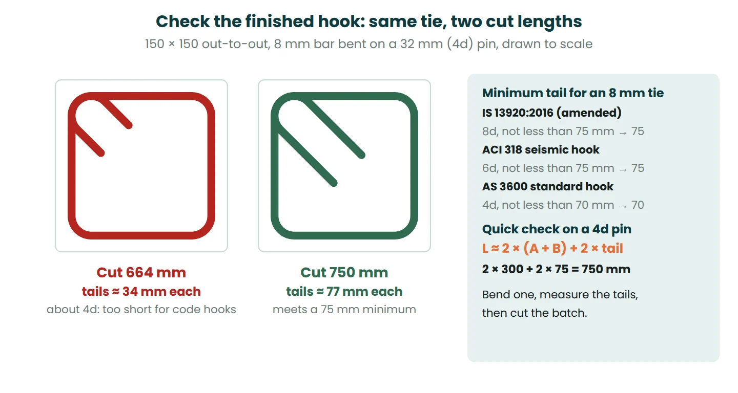
So treat 664 mm as the schedule figure that bar benders and estimators expect. For seismic work, or any drawing that states a minimum tail, let the trial bend set the cut length.
Worked example 2: a 300 × 450 mm beam
Beam 300 × 450 mm, 10 mm stirrups, 25 mm clear cover, 135° hooks.
- Out-to-out: A = 300 − 2 × 25 = 250 mm and B = 450 − 2 × 25 = 400 mm.
- Perimeter: 2 × (250 + 400) = 1,300 mm.
- Hooks: 10 × 10 = 100 mm each, 200 mm for two.
- Deductions: 3 × 2 × 10 + 2 × 3 × 10 = 60 + 60 = 120 mm.
- Cutting length: 1,300 + 200 − 120 = 1,380 mm.
Run the hook check here too. On a 40 mm (4d) pin, a 1,380 mm bar leaves tails of about 42 mm. If the beam is detailed to IS 13920 with 80 mm tails (8d for a 10 mm bar), the quick check gives 2 × 650 + 2 × 80 = 1,460 mm.
How many stirrups: spacing along the member
For each zone, n = zone length ÷ spacing + 1, with the number of spaces rounded up. Where two zones meet, count the boundary stirrup once.
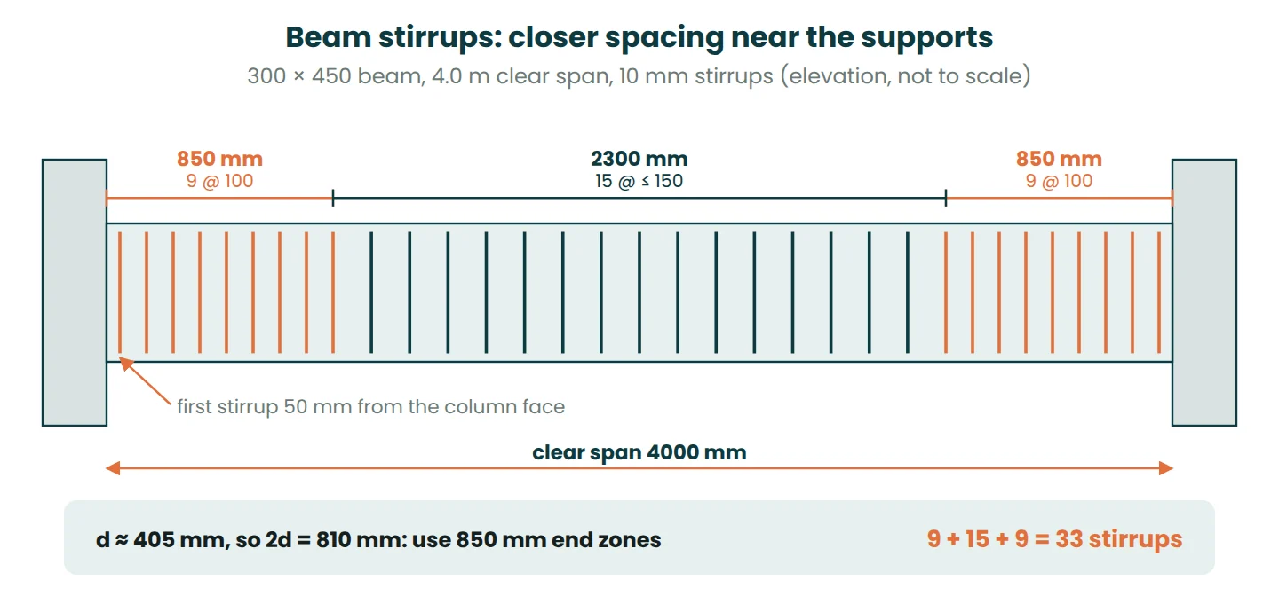
Beams usually have closer stirrups near the supports, where shear is highest. In ductile frames to IS 13920, the first hoop sits within 50 mm of the column face, hoops stay closely spaced over twice the effective depth (2d) at each end at no more than the least of d/4, a multiple of the smallest main bar diameter and 100 mm, and the rest of the span may go up to d/2.
Example: the 300 × 450 beam above, 4.0 m clear span, 20 mm main bars. The effective depth is about 450 − 25 − 10 − 10 = 405 mm, so 2d = 810 mm. Use 850 mm end zones at 100 mm, and 150 mm in the middle (d/2 is about 200 mm).
- Each end zone, from 50 mm to 850 mm at 100 mm: (850 − 50) ÷ 100 + 1 = 9 stirrups.
- Middle: the gap between the last end-zone stirrups is 4,000 − 2 × 850 = 2,300 mm. 2,300 ÷ 150 = 15.3, so 16 spaces and 15 stirrups at about 144 mm.
- Total: 9 + 15 + 9 = 33 stirrups.
For the 230 × 230 column with a 3.0 m clear height and ties at 150 mm: 3,000 ÷ 150 + 1 = 21 ties. IS 456 limits the tie pitch to the least of the smallest column dimension, 16 times the smallest main bar and 300 mm. With 12 mm bars that is 192 mm, so 150 mm is fine. Add any ties the drawings show through the beam-column joint.
Bar bending schedule with weights
Steel weighs about 7,850 kg/m³, so a bar of diameter D mm weighs 7,850 × π ÷ 4 × D² ÷ 1,000,000 kg per metre, which simplifies to D² ÷ 162 kg/m. An 8 mm bar is 64 ÷ 162 = 0.395 kg/m and a 10 mm bar is 0.617 kg/m.
| Bar mark | Member | Dia (mm) | Shape | Cut length (mm) | No. | Total length (m) | kg/m | Weight (kg) |
|---|---|---|---|---|---|---|---|---|
| T1 | Column 230 × 230 | 8 | Closed tie, 135° hooks | 664 | 21 | 13.94 | 0.395 | 5.51 |
| S1 | Beam 300 × 450 | 10 | Closed stirrup, 135° hooks | 1,380 | 33 | 45.54 | 0.617 | 28.11 |
| Total | 33.62 |
The rebar weight calculator uses the full steel density instead of the 162 shortcut, so it shows 5.50 kg and 28.08 kg; the difference is in the third figure. If the trial bend sends the column ties to 750 mm, that line becomes 21 × 0.750 = 15.75 m and 6.22 kg. For the main bars in the same cages, the lap length calculator gives the lap to add where bars are joined.
Common mistakes
- Subtracting cover from the wrong face. If the 40 mm in the example is to the main bars, the tie is 166 mm out-to-out and the calculator gives 728 mm. A stirrup that is too small pulls the main bars inwards; one that is too big leaves the cover short.
- Taking the bar diameter off twice. Out-to-out sizes take the full bend deductions. Centreline sizes (member − 2 × cover − d) have already lost the bar diameter, so they need only about 1d per 90° bend. Using centreline sizes with the full deductions gives a bar that is too short.
- Forgetting the deductions on other shapes. On a closed stirrup the extra length only lengthens the tails, but on an L-bar or U-bar it lengthens a leg, which can eat into the end cover.
- Hooks that do not meet the seismic rule. 90° hooks in a ductile frame, tails shorter than the code minimum, or hooks that do not wrap round a main bar. Bend a sample and measure it.
- Counting stirrups without the +1, or counting the boundary stirrup in both zones.
To schedule your own members, put each size through the bar cutting length calculator, then total the weights with the rebar weight calculator. The concrete volume guide covers the concrete for the same elements, and the pre-pour inspection checklist covers checking ties, spacing and cover before the pour.
Frequently asked questions
What is the formula for stirrup cutting length?
Cutting length = 2 × (A + B) + 2 × hook − bend deductions, where A and B are the out-to-out stirrup sizes (member size minus twice the clear cover). With 10d hooks, 2d per 90° bend and 3d per 135° bend, it simplifies to 2 × (A + B) + 8d.
What is the cutting length of an 8 mm stirrup for a 230 × 230 column?
It is 664 mm by the standard formula, with 40 mm clear cover and 10d hooks. If the drawing needs finished tails of at least 75 mm, plan on about 750 mm and confirm it with a trial bend.
Why do stirrups have 135° hooks?
A 135° hook wraps round a main bar and anchors its tail in the concrete core, so the stirrup stays closed if the cover spalls in an earthquake. A 90° hook sits in the cover and can open.
How do I calculate the weight of stirrups?
Multiply the total length in metres by D² ÷ 162 kg/m. Twenty-one 8 mm ties at 664 mm are 13.94 m × 0.395 kg/m = 5.51 kg.
References
- Bureau of Indian Standards. IS 13920:2016, Ductile design and detailing of reinforced concrete structures subjected to seismic forces: code of practice, with Amendment No. 1 (2017) and Amendment No. 2 (2020). archive.org
- Bureau of Indian Standards. IS 13920:1993, Ductile detailing of reinforced concrete structures subjected to seismic forces: code of practice. law.resource.org
- Bureau of Indian Standards. IS 456:2000, Plain and reinforced concrete: code of practice. law.resource.org
- Bureau of Indian Standards. IS 2502:1963, Code of practice for bending and fixing of bars for concrete reinforcement.
- American Concrete Institute. ACI 318-19, Building code requirements for structural concrete and commentary.
- Standards Australia. AS 3600, Concrete structures.
This article is general information for learning and planning. Always follow your project specification, the current standard and the advice of the responsible engineer.


Leave a Reply