
Setting out a building means transferring the positions and levels on the approved drawings onto the ground, as pegs, string lines and marks that the excavator, concretor and bricklayer can build from. On a small building the sequence is: fix a baseline from the boundary or survey control, set the main corners, prove the right angles with the 3-4-5 method and the diagonals, put up profile boards so the lines survive the excavation, and carry levels across from the benchmark.
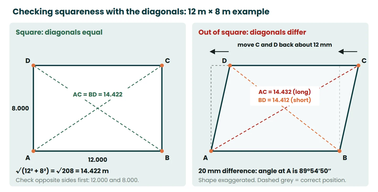
Every step has a check, and the checks matter more than the method. A 12 m × 8 m building is square when both diagonals measure 14.422 m. This guide works through that example, shows what a 20 mm difference in the diagonals really means, and lists the mistakes that put footings in the wrong place.
You can check corner coordinates, side lengths and bearings with the free land area calculator, and check a level run with the levelling calculator.
What setting out is and who is responsible
Setting out fixes two things: where the building sits on plan, and how high its floors and footings are. Get the plan position wrong and the building can end up over a setback line or a boundary. Get the levels wrong and you fight drainage, steps and floor heights for the life of the building.
Under most construction contracts the builder or contractor is responsible for setting out the works correctly from the reference points and levels the client provides, and for fixing its own setting-out errors at its own cost. If the information supplied was wrong, the cost usually falls back on the client. Read the setting-out clause in your contract before you start, because it decides who pays when a footing has to move.
Anything tied to a legal boundary needs a licensed surveyor. In New South Wales, the Board of Surveying and Spatial Information treats setting out a building at fixed offsets from the boundaries as a land survey, which must be done by or under a registered land surveyor. Other states and countries have their own rules. On most house jobs the surveyor pegs the building corners or offset pegs, and the site team builds from those pegs and checks them.
Preparation before setting out a building
- Current approved drawings. Check the revision on the site plan, footing plan and set-out plan. Add up the running dimensions and confirm they equal the overall dimensions. A drawing that does not add up is far cheaper to query now than after the pour.
- Survey control and benchmarks. Get the coordinates of the control marks and the benchmark RL, with its datum (AHD or a site datum). If there are two benchmarks, level between them to prove they agree.
- Boundary pegs. Find them and confirm they are the surveyor’s pegs. A fence is not a boundary. If a peg is missing or looks disturbed, call the surveyor rather than guessing.
- Coordinates. For instrument work, list the coordinates of every corner and grid line. Compute the side lengths and diagonals from those coordinates before you go out, so you know what the checks should read.
- Site fall. Take a few spot levels and work out the fall across the pad with the slope calculator. A steep fall tells you early that tapes must be stepped and that profile boards will sit at very different heights.
- Equipment. A steel tape in good condition, string line, pegs, nails, timber for profiles, spray paint, a level and staff (checked with a two-peg test), and a total station or builder’s square if you have one.
Setting out a building step by step
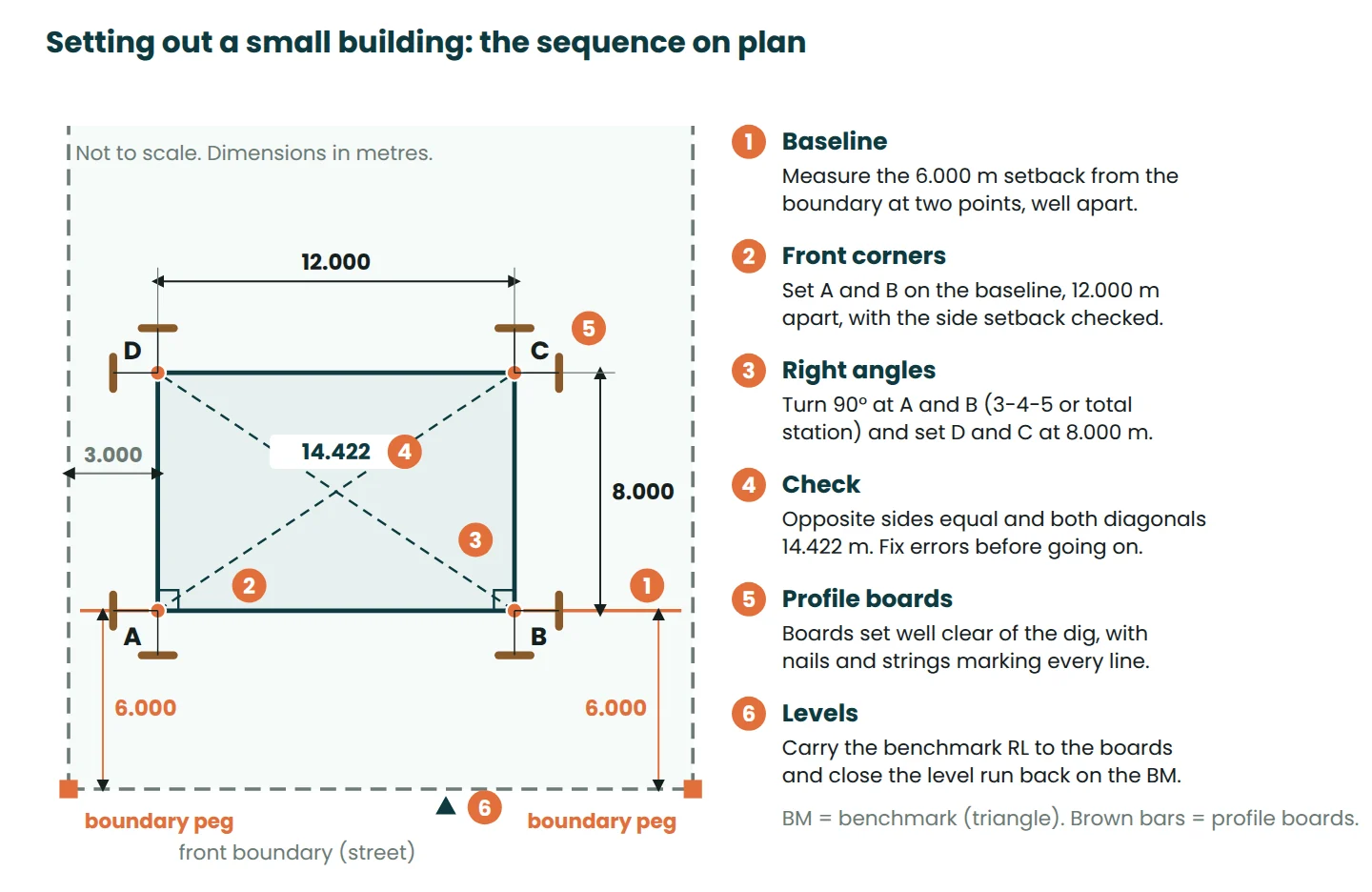
The example is a simple 12.000 m × 8.000 m rectangle with a 6.000 m front setback and a 3.000 m side setback. The same steps work for an L-shaped or stepped plan: break it into rectangles and check each one.
1. Establish a baseline
Measure the 6.000 m setback square off the front boundary at two points, as far apart as the site allows, and run a string between them. That string is the front wall line and your baseline. Two well-separated points control the direction far better than one point and a guess. If the surveyor has given you control marks or offset pegs, build the baseline from those instead.
2. Set the main corners
Measure the 3.000 m side setback to fix corner A on the baseline, then measure 12.000 m along the baseline to B. Drive a peg at each and put a nail in the top at the exact point.
3. Prove the right angles
Turn 90° at A and B and measure 8.000 m to set D and C. On a square lot with the building parallel to the side boundary, D should also measure 3.000 m from that boundary. Without an instrument, use the 3-4-5 method: a triangle with sides 3, 4 and 5 always has a right angle between the 3 and 4 sides, because 3² + 4² = 5². Then check the whole rectangle: both pairs of opposite sides equal, and both diagonals equal. The diagonals are the final word, because a shape with equal opposite sides and equal diagonals has to be a rectangle.
4. Put up profile boards and offset pegs
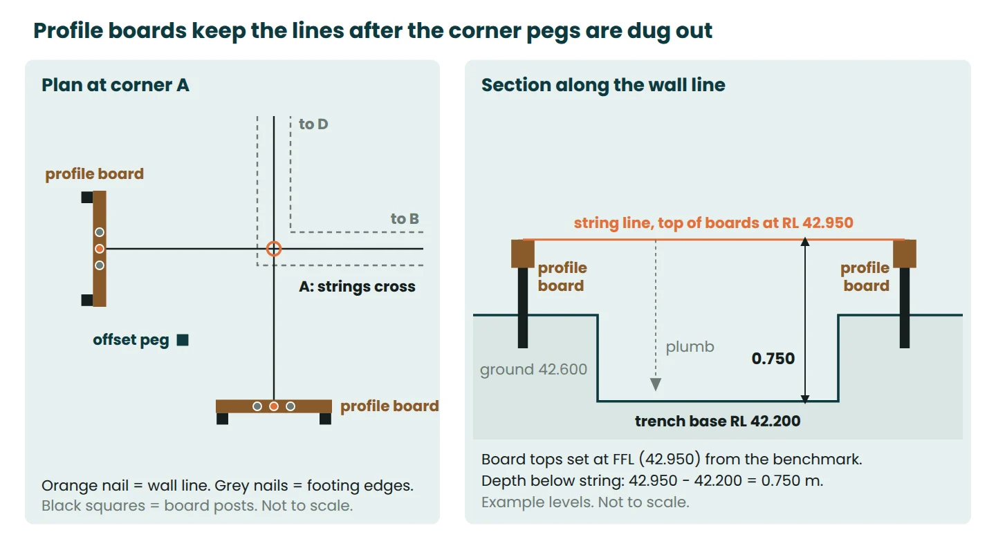
Corner pegs do not survive an excavator. Profile boards (also called batter boards) are horizontal boards nailed to two posts, set well clear of the dig and across the line of each wall. Strings stretched between opposite boards re-create every line whenever you need it. Mark each board with nails or saw cuts for the wall line and both footing edges, and write on the board what each mark is. Add offset pegs at a recorded distance from key corners, outside the work area, so a corner can be re-established even if a board is hit.
5. Transfer levels from the benchmark
Set up the level, take a backsight on the benchmark, and work out the height of the instrument. Say the benchmark is RL 42.350 and the backsight reads 1.425: the instrument height is 42.350 + 1.425 = 43.775. To set a board top at the finished floor level of 42.950, the staff standing on the board must read 43.775 − 42.950 = 0.825. Mark that height on the posts and fix the board to the marks. With every board top at FFL, the trench base at RL 42.200 is simply 0.750 m below the string. Close the level run back on the benchmark before you trust any of it. The rise and fall method article shows how to book and check that run.
6. Check again after excavation
Once the trenches are dug, re-string the lines from the profiles, plumb down, and check trench positions, widths and base levels. Machines bump boards, and spoil heaps bury pegs. Then check the formwork and steel before concrete with a pre-pour inspection checklist.
Worked examples
Diagonal of a 12 m × 8 m rectangle
By Pythagoras, d = √(12² + 8²) = √(144 + 64) = √208 = 14.422 m. Both diagonals, AC and BD, should read 14.422 m. Work the figure out in the office and write it on the set-out sheet, so nobody is doing square roots in the rain.
Scaling the 3-4-5 triangle
Any multiple of 3-4-5 works: 6-8-10, 9-12-15 and so on. Bigger is better, because the same tape error matters less on a bigger triangle. The table shows what happens if the long side is misread by 5 mm, and how far that throws the far end of the 8 m wall sideways.
| Triangle (m) | Long side | Angle error from a 5 mm misread | Sideways error at 8 m |
|---|---|---|---|
| 3-4-5 | 5.000 | 7.2′ (0.12°) | 16.7 mm |
| 6-8-10 | 10.000 | 3.6′ (0.06°) | 8.3 mm |
| 9-12-15 | 15.000 | 2.4′ (0.04°) | 5.6 mm |
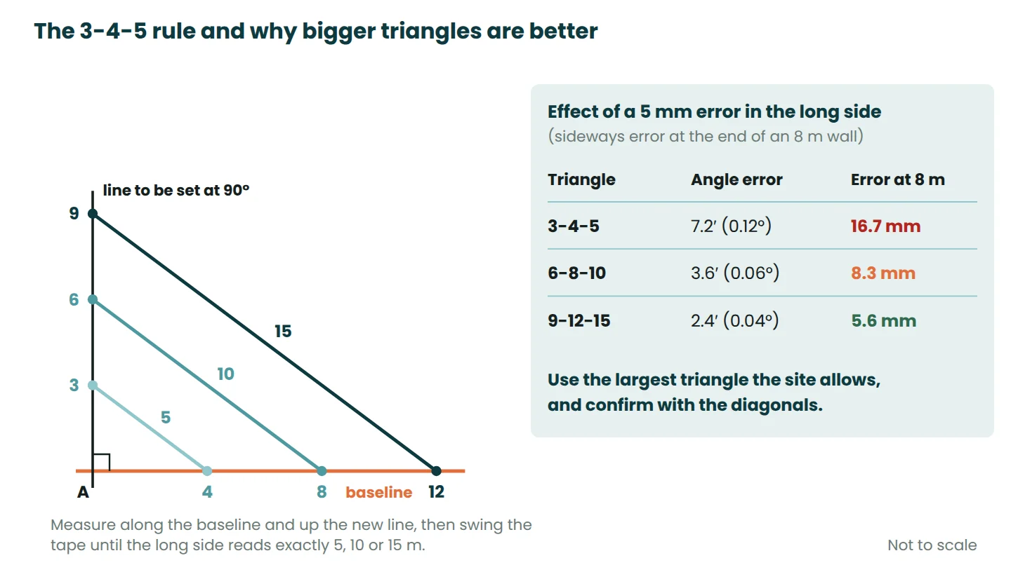
On this building, a 9-12-15 triangle with the 12 m leg along the baseline and the 9 m leg up the side wall line (running 1 m past corner D) is the obvious choice.
What a 20 mm diagonal difference means
Suppose the sides check at 12.000 and 8.000 but AC reads 14.432 and BD reads 14.412. The rectangle has become a slight parallelogram. Working back, the angle at A is 89°54′50″, about 5′10″ (0.086°) short of a right angle, and corners C and D are each about 12 mm too far along the 12 m direction. Each diagonal is roughly half the difference (10 mm) away from the true 14.422.
The fix: hold A and B, move C and D about 12 mm in the direction that shortens the long diagonal, then measure both diagonals again. Twelve millimetres sounds small, but it shows up in wall frames, roof trusses and floor tiles laid against a wall. Find it at the pegs, not when the frame arrives.
Total station and GNSS setting out on larger jobs
On larger sites, tapes give way to instruments. A total station is set up over a control mark and oriented on a second mark, or set up anywhere and positioned by resection from three or more marks. Check on a further control mark before staking anything. The instrument then sets out each point from its coordinates. Check the result independently: tape between set-out points, compare with the computed distances, and re-observe key points from a different set-up.
RTK GNSS is quick for bulk earthworks, roads and large pads, but it is less precise than a total station, and weaker in height than in plan. Studies of network RTK have typically found horizontal errors of about 1 to 2 cm and vertical errors of about 2 to 3 cm. That suits bulk earthworks, but not holding-down bolts or slab edge formwork. Tie the receiver to the project grid and height datum on known control marks, and check a known mark at the start of every session.
Tolerances and checks
Working tolerances for setting out come from your project specification and the engineer’s notes. ISO 4463-1 gives permissible deviations for setting out and measurement on building sites. For finished houses, Victoria’s Guide to Standards and Tolerances 2026 from the Building and Plumbing Commission gives the points at which work is treated as defective. Under it, a set-out is out of tolerance if any part of the building encroaches over a boundary (unless the regulations allow it), and the external dimensions of habitable buildings are out if they deviate by more than L/200 or 10 mm, whichever is greater.
Read those as limits for disputes, not targets. L/200 on a 12 m wall is 60 mm. A slab 60 mm short is still a problem for a prefabricated frame and for every drawing that follows. The same guide treats a finished floor level more than 40 mm from the documented level as a defect. Aim for the specification, and check every step so errors are caught while they are still cheap.
| Stage | Check | Why |
|---|---|---|
| Before starting | Drawing revision, running dimensions add up, benchmark RL and datum confirmed | Most setting-out errors start in the office |
| Baseline | Setback measured at two points; baseline tied to boundary pegs or control | Direction errors grow along the building |
| Corners | Opposite sides equal; both diagonals equal to the computed value | Proves the plan is square and the right size |
| Profile boards | Strings re-checked against the corner pegs before excavation | Boards are often knocked while being fixed |
| Levels | Level run closed back on the benchmark; RLs written on boards | An open level run cannot show a field error |
| After excavation | Trench position, width and base level from the strings | Machines move boards and bury pegs |
| Before the pour | Formwork lines, set-downs and levels checked again | The last chance to move anything cheaply |
Common mistakes when setting out a building
Measuring from the wrong face. Set-out plans may dimension to the slab edge, the frame, the outside of the brickwork or a grid line, and they are all different. Confirm which face every dimension refers to, and write it on the profile boards.
Sagging or sloping tapes. Dimensions on drawings are horizontal. A tape laid on sloping ground or sagging between supports reads more than the horizontal distance, so the point you set ends up short. Measure 12.000 m along ground that rises 0.5 m and the true horizontal distance is only 11.990 m, 10 mm short. With a 1.0 m rise it is 42 mm short. Hold the tape level, step it down slopes, and pull to an even tension.
Disturbed pegs and boards. A peg that has been driven over still looks like a peg. Check strings against offset pegs each morning, and re-check anything that has been hit before you build from it.
Not re-checking after excavation. Trenches are dug to the paint on the ground, not to the strings. Re-string and plumb down before steel goes in, not after the concrete truck is booked.
Trusting fences and old marks. Fences are often off the boundary. Work only from the surveyor’s pegs and control.
No independent check. The person who set the corners will tend to repeat their own mistake. Have someone else measure the diagonals, ideally with a different tape.
When the pegs are in, enter the corner coordinates in the land area calculator to confirm the side lengths, bearings and area match the drawings before excavation starts.
Frequently asked questions
How do you check that a building is square?
Measure both diagonals: if the opposite sides are equal and the diagonals match, the rectangle is square. For a 12 m × 8 m building both diagonals should read 14.422 m.
What is the 3-4-5 rule in construction?
It is a way to set a right angle with a tape: measure 3 m along one line and 4 m along the other, and the corner is 90° when the distance between those points is exactly 5 m. Multiples such as 6-8-10 or 9-12-15 are more accurate.
What are profile boards used for?
They hold the building lines and levels clear of the excavation. Strings stretched between marked boards re-create each wall and footing line, and board tops set to a known RL give a reference for trench depths.
Who is responsible for setting out a building?
The builder or contractor usually is, under the contract, working from reference points and levels supplied by the client. Work tied to legal boundaries generally needs a licensed or registered surveyor.
References
- Building and Plumbing Commission, Victoria (2026). Guide to Standards and Tolerances 2026, section 2: Setting out.
- Board of Surveying and Spatial Information, NSW (2024). What is a ‘Land Survey’? Edition 3.
- ISO 4463-1:1989. Measurement methods for building: Setting-out and measurement, Part 1: Planning and organization, measuring procedures, acceptance criteria.
- Weaver, B., Gillins, D.T. and Dennis, M. Hybrid Survey Networks: Combining Real-Time and Static GNSS Observations for Optimizing Height Modernization. Journal of Surveying Engineering (ASCE), author manuscript, NOAA Institutional Repository.
- Intergovernmental Committee on Surveying and Mapping (2020). Guideline for Control Surveys by Differential Levelling, Special Publication 1, Version 2.2.
This article is general information for learning and planning. Always follow your project specification, the current standard and the advice of the responsible engineer or surveyor.

Leave a Reply