
A microscope is an instrument that makes small things look bigger and shows detail your eye cannot separate on its own. The one used in school and university labs is the compound light microscope. It shines light through a thin specimen and magnifies it twice: first with an objective lens, then with an eyepiece. The parts of a microscope fall into three groups. Optical parts magnify, illumination parts light the specimen, and mechanical parts hold everything in line and move it into focus.
In short: magnification comes from two lenses multiplied together, contrast comes from the condenser and iris diaphragm, and focus comes from the two focus knobs. One rule matters more than any label. Start on the lowest power every time, and once the 40× objective is in place, use only the fine focus knob. Ignoring that rule is how slides get cracked and lenses get scratched.
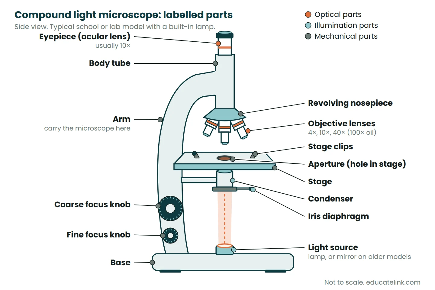
Labelled diagram of a compound light microscope
The diagram shows a typical student microscope from the side, with a lamp in the base. Older models use a mirror instead, and many lab models have a mechanical stage instead of clips.
Parts of a microscope and their functions
The table follows the grouping used in lab training material such as the CDC’s sections of the microscope job aid. In an exam, “ocular” and “eyepiece” mean the same lens, and “aperture” and “stage opening” mean the same hole.
| Group | Part | Function |
|---|---|---|
| Optical | Eyepiece (ocular lens) | Magnifies the objective’s image again, usually 10×. |
| Optical | Objective lenses | Form the first magnified image. Usually 4×, 10×, 40× and often 100× oil immersion. |
| Mechanical | Body tube | Holds the eyepiece and objectives the correct distance apart. |
| Mechanical | Revolving nosepiece | Holds the objectives and turns to click each one into the light path. |
| Mechanical | Arm | Joins the head to the base. Carry the microscope by it. |
| Mechanical | Stage | Flat platform that holds the slide. |
| Mechanical | Stage clips or mechanical stage | Hold the slide still. A mechanical stage also moves it with two knobs. |
| Mechanical | Aperture | Hole in the stage that lets light up through the specimen. |
| Mechanical | Coarse focus knob | Moves the stage quickly to find the specimen. Low power only. |
| Mechanical | Fine focus knob | Small movements to sharpen the image. The only knob to use at 40× and 100×. |
| Mechanical | Base | Stable foot that supports the microscope and usually houses the lamp. |
| Illumination | Light source (lamp or mirror) | Supplies the light. A mirror reflects daylight or lamp light up through the stage. |
| Illumination | Condenser | Lenses under the stage that gather the light and focus it onto the specimen. |
| Illumination | Iris diaphragm | Ring of thin metal leaves that sets the width of the light cone, changing contrast and brightness. |
Reading the numbers on an objective
An objective marked 40/0.65 magnifies 40 times and has a numerical aperture (NA) of 0.65. NA measures how wide a cone of light the lens collects; higher NA means finer detail. A line such as 160/0.17 gives the design tube length and coverslip thickness in millimetres. Colour rings are common: red 4×, yellow 10×, light blue 40×, white 100×, plus black on oil lenses.
How light travels through a microscope
Light runs straight up the middle. The iris diaphragm sets the width of the beam and the condenser focuses it into a bright patch on the specimen. Parts of the specimen that absorb or scatter more light look darker, which is why specimens must be thin and why stains help.
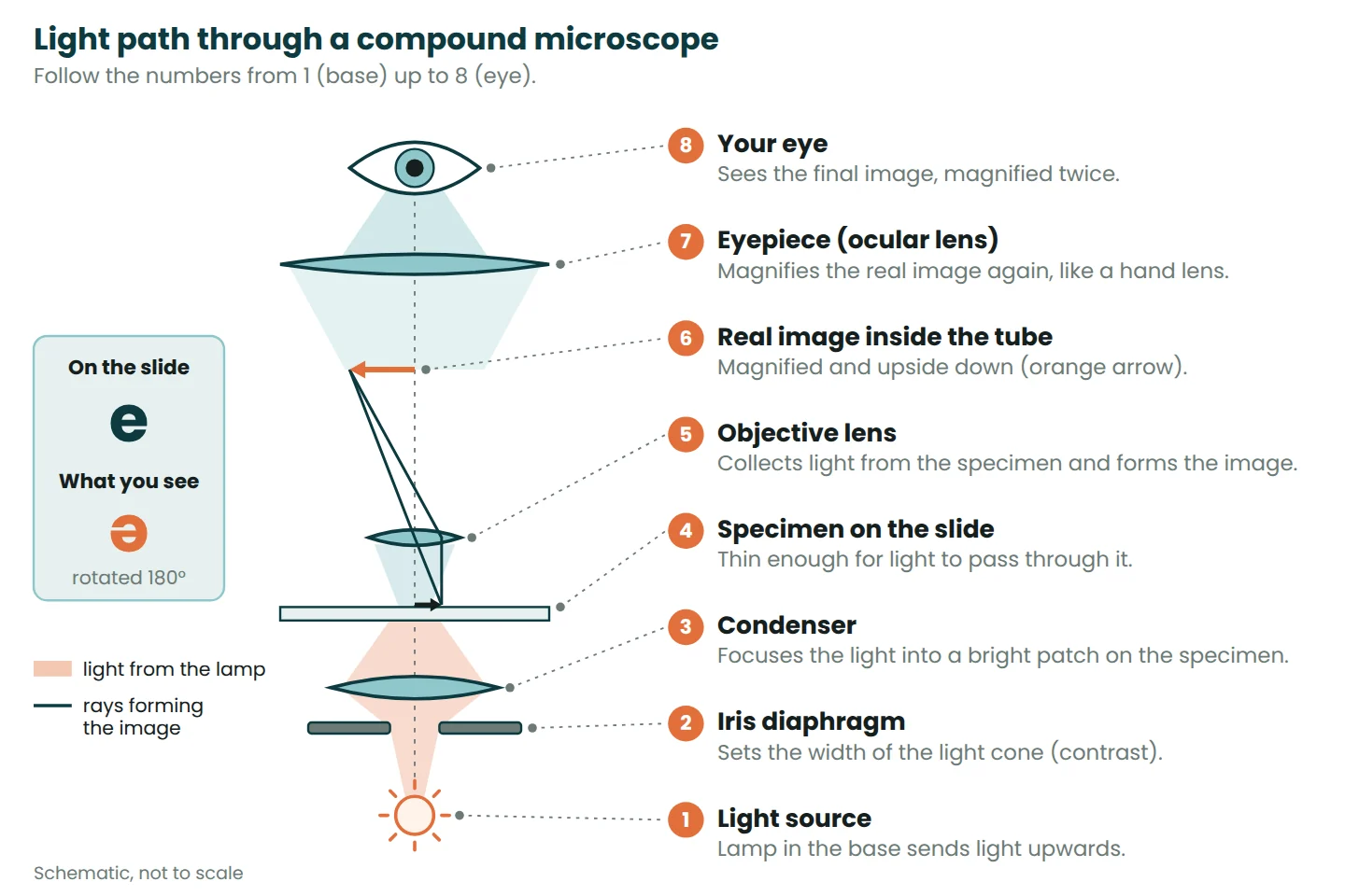
The objective forms a real, magnified image inside the body tube, and that image is upside down. The eyepiece works like a hand lens on it and magnifies it again without turning it back. So a letter “e” on a slide looks rotated by 180°, and when you move the slide left, the image moves right. Expect this the first time you chase a swimming organism around a drop of pond water.
Total magnification
Multiply the two lens powers: total magnification = eyepiece × objective. With a 10× eyepiece and a 40× objective, the total is 10 × 40 = 400×.
| Objective (NA) | Total with 10× eyepiece | Field of view diameter | Working distance |
|---|---|---|---|
| 4× (0.10) | 40× | 4.5 mm | 30 mm |
| 10× (0.25) | 100× | 1.8 mm | 7 mm |
| 40× (0.65) | 400× | 0.45 mm | 0.65 mm |
| 100× oil (1.25) | 1000× | 0.18 mm | 0.23 mm |
Field diameters assume an eyepiece with a field number of 18 mm. Working distance (objective tip to slide) is from one maker’s standard achromat range, Nikon CFI Achromat. Other brands differ a little, but a standard 40× lens sits under a millimetre above the slide.
Worked example: when more magnification adds nothing
A student fits a 15× eyepiece to the 40×/0.65 objective: 15 × 40 = 600×. A common rule of thumb says useful magnification lies between 500 and 1000 times the objective’s NA. For NA 0.65 that is 325× to 650×, so 600× still shows real detail.
With a 25× eyepiece the total is 1000×, well past 650×. The image grows but no new detail appears. This is empty magnification: finer detail needs a higher NA objective, not a stronger eyepiece.
Field of view and estimating cell size
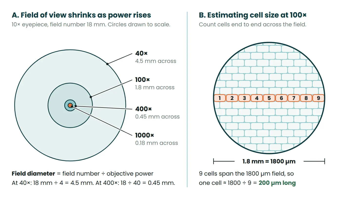
The field of view is the bright circle you see. Its real diameter on the slide shrinks as magnification rises. Find it in one of two ways:
- From the field number:
field diameter = field number ÷ objective magnification. Many eyepieces show it, for example “10×/18”. - From a measurement: count millimetre divisions of a clear ruler across the circle at low power, then scale with
FOV₂ = FOV₁ × M₁ ÷ M₂, where M is total magnification.
Worked example: how long is an onion cell?
- At 40× total, the ruler shows the field is 4.5 mm across.
- At 100× the field is 4.5 × 40 ÷ 100 = 1.8 mm, which is 1.8 × 1000 = 1800 µm.
- Nine onion epidermis cells lie end to end across the middle of the field.
- One cell ≈ 1800 ÷ 9 = 200 µm long (0.2 mm).
Count along a diameter, include part cells as fractions and average two or three counts. For accurate sizes, labs use an eyepiece graticule calibrated against a stage micrometer.
Resolution and why oil immersion helps
Resolution is the smallest distance between two points that still look separate. Without it, a bigger image is just a bigger blur. It depends on the wavelength of light (λ) and the objective’s NA: d = λ ÷ (2 × NA), where NA = n × sin θ. n is the refractive index of the medium between coverslip and lens, and θ is half the angle of the accepted light cone.
With green light at 550 nm, a 40×/0.65 objective gives d = 550 ÷ 1.3 ≈ 423 nm (0.42 µm). A 100× oil objective with NA 1.25 gives 550 ÷ 2.5 = 220 nm, and the best oil objectives at NA 1.40 give about 196 nm. That is why about 0.2 µm (200 nm) is quoted as the limit of the light microscope. Nikon’s MicroscopyU notes on resolution put the real-world best at about 0.25 µm, and poor contrast or lighting often prevents even that.
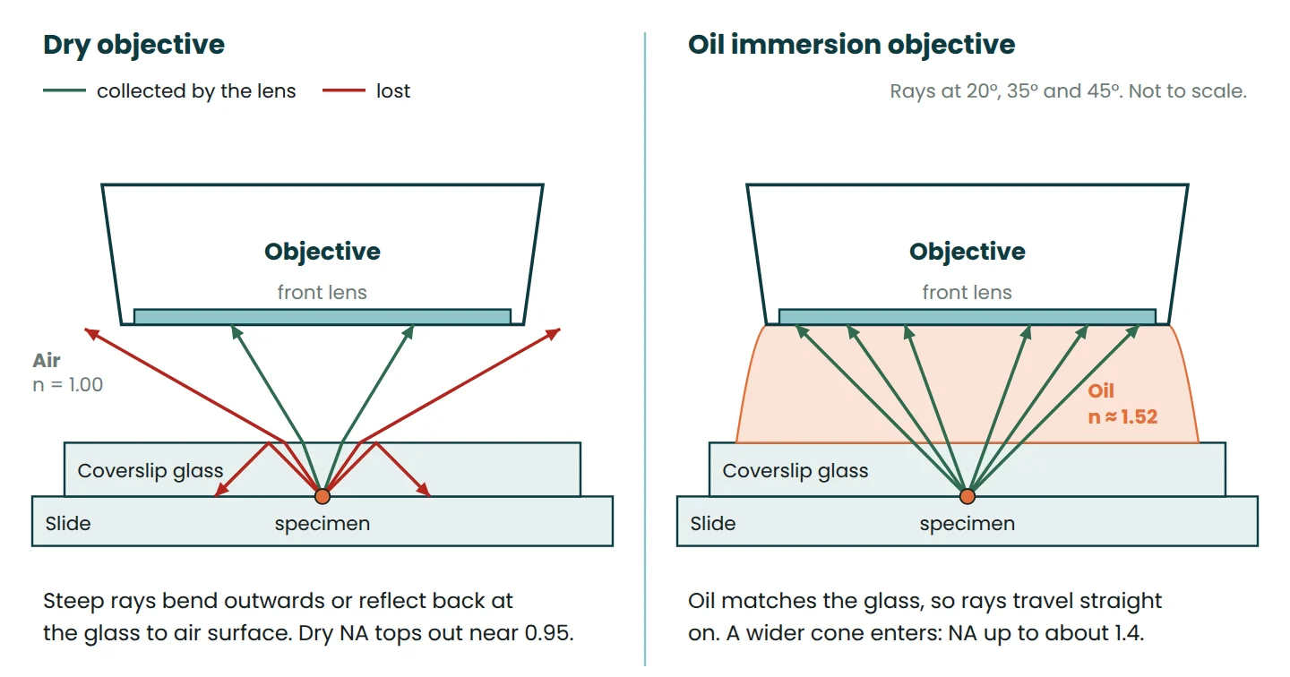
With a dry objective, air (n = 1.00) fills the gap. Light leaving the glass bends outwards, and rays steeper than about 41° in the glass are reflected back into it, so the lens never collects them. Dry objectives top out near NA 0.95. Immersion oil has almost the same refractive index as glass (about 1.51 to 1.52), so those rays carry straight on into the lens. NA rises to about 1.4 and the resolvable distance drops from about 0.29 µm to 0.20 µm.
That is still enough to see chromosomes, which carry the genes behind Mendel’s law of segregation, when they condense during cell division.
How to focus a microscope step by step
Start on the lowest power for three reasons. The field is widest (4.5 mm), so the specimen is easy to find. The working distance is longest (30 mm against 0.65 mm at 40×), so the lens cannot hit the slide. And depth of field is greatest (it shrinks with the square of the NA), so more of the specimen is sharp at once.
- Switch on the lamp at low to medium brightness and click the 4× objective into place.
- Put the slide on the stage, coverslip up, with the specimen over the aperture. Secure it.
- Watching from the side, use the coarse knob to raise the stage to its highest position under the objective.
- Look through the eyepiece and turn the coarse knob slowly to lower the stage until the specimen appears. Sharpen with the fine knob.
- Adjust the iris diaphragm until edges look crisp. Unstained cells usually show up better with less light.
- Centre the part you want, turn to 10× and refocus with the fine knob. Lab microscopes are usually parfocal, so the image stays nearly in focus.
- Centre again and turn to 40×. Fine focus only. The image will be darker, so open the iris diaphragm or turn up the lamp.
- For 100×, focus at 40×, swing the nosepiece halfway, add one drop of immersion oil to the coverslip and click the 100× into it. Fine focus only, and never swing the 40× back through the oil.
How to prepare a wet mount
A wet mount is a temporary slide with the specimen in a drop of liquid under a coverslip. It suits onion epidermis, cheek cells and pond water, where what lives in the sample depends on abiotic factors such as light and temperature.
- Put one drop of water or stain in the centre of a clean slide.
- Lay a thin, single layer of specimen flat in the drop, such as onion skin peeled from inside a scale leaf.
- Hold the coverslip at about 45° with one edge touching the drop, and let the liquid spread along that edge.
- Lower it slowly with a mounted needle so air is pushed out, not trapped.
- Blot extra liquid. To stain later, add stain at one edge and draw it under with paper towel at the other.
Iodine solution is the usual stain for onion cells and methylene blue for cheek cells; both make the nucleus easier to see. A stain is a dye (the solute) dissolved in a liquid (the solvent), terms explained in our note on solutes and solvents.
Care and handling
- Carry it upright with two hands: one on the arm, one under the base.
- Clean lenses only with lens paper, plus lens cleaner if needed. Tissues and clothing can scratch the coatings.
- Wipe oil off the 100× objective after every session and check the 40× has not picked any up.
- Before packing away: remove the slide, wipe the stage, click the lowest power objective into place, lower the stage, switch off, unplug by the plug and fit the dust cover.
Types of microscopes compared
| Type | How it works | Typical magnification | Resolution | Best for |
|---|---|---|---|---|
| Compound light | Visible light passes through a thin specimen; two lens systems | 40× to about 1000× (useful limit about 1400× with NA 1.4 oil lenses) | About 0.2 µm (200 nm) | Cells, tissues, bacteria (with oil), living specimens in colour |
| Stereo (dissecting) | Two light paths give a 3D view; mostly reflected light | About 10× to 50× | Lower than a compound microscope | Insects, flowers, dissections. Long working distance (110 mm on one common model) |
| Transmission electron (TEM) | Electrons pass through an ultra-thin section (about 100 nm) in a vacuum | Over 1,000,000× on high-end instruments | As fine as 0.05 nm on the best instruments | Inside cells: membranes and organelles, as 2D black-and-white images |
| Scanning electron (SEM) | An electron beam scans the surface of a coated sample | Over 1,000,000× on high-end instruments | About 1 to 20 nm | Surface shape, as 3D-looking black-and-white images |
Electrons have a far shorter wavelength than visible light, which is why electron microscopes show more detail. But specimens sit in a vacuum after heavy preparation, so living cells cannot be watched. Syllabuses round these figures differently; use the values yours gives.
Common mistakes
- Coarse focus at 40× or 100×. The working distance is under a millimetre, so one careless turn can crack the slide or scratch the front lens.
- Too much light. It washes out unstained cells. Turn the lamp down or close the iris diaphragm a little, but not right down, which loses fine detail.
- Not centring before switching up. Anything near the edge at 10× will be outside the 40× field.
- Dirty lenses. A speck that turns with the eyepiece is on the eyepiece; one that moves with the slide is on the slide. Otherwise check the objective.
- Air bubbles mistaken for cells. Bubbles are perfect circles with thick dark rims. Lower the coverslip at an angle.
- Mixing millimetres and micrometres. 1 mm = 1000 µm. Convert before you divide.
Practice questions
In write-ups, record the magnification beside every drawing. For the rest of the structure, see our guide on how to write a lab report.
1. A microscope has a 10× eyepiece and 4×, 10× and 40× objectives. What total magnifications can it give?
Answer: 10 × 4 = 40×, 10 × 10 = 100× and 10 × 40 = 400×.
2. The field of view is 4.5 mm at 40× total. What is it at 400×?
Answer: 4.5 × 40 ÷ 400 = 0.45 mm, or 450 µm.
3. At 400× (field 450 µm), about 58 red blood cells fit side by side across the field. How wide is one?
Answer: 450 ÷ 58 ≈ 7.8 µm, close to the published average of about 7.7 µm for human red blood cells.
4. Can a 40×/0.65 objective separate two structures 0.3 µm apart in 550 nm light?
Answer: No. d = 550 ÷ (2 × 0.65) ≈ 423 nm = 0.42 µm, which is larger than 0.3 µm, so the two blur into one. A 100×/1.25 oil objective resolves 0.22 µm and would show them as two.
5. A drawing of a 200 µm onion cell is 45 mm long. What is its magnification?
Answer: Use the same units: 45 mm = 45,000 µm. Magnification = image size ÷ actual size = 45,000 ÷ 200 = 225×.
Frequently asked questions
What does the iris diaphragm do on a microscope?
It controls the width of the cone of light reaching the specimen, which changes contrast and brightness. Leave it partly open and set brightness with the lamp.
Why is the image in a microscope upside down?
The objective forms an inverted real image and the eyepiece magnifies it without turning it back. The view is rotated 180°, so the image moves the opposite way to the slide.
What is the maximum magnification of a light microscope?
Useful magnification tops out at roughly 1000× to 1400× (1000 × NA 1.4 for the best oil objectives). Beyond that is empty magnification, because resolution stops at about 0.2 µm.
More revision topics are in the EducateLink study notes.
References
- Centers for Disease Control and Prevention. Sections of the Microscope (laboratory job aid).
- Nikon MicroscopyU. Resolution.
- Nikon MicroscopyU. Useful Magnification Range.
- Evident Scientific. Numerical Aperture.
- Nikon Instruments. CFI Achromat objective specifications.
- College of the Canyons, Introduction to Microbiology lab manual (LibreTexts). Microscopy: Materials and Procedures.
- University of Liverpool, ChemTube3D. Electron Microscopy.
- BioNumbers, Harvard Medical School. Red blood cell diameter.
This note is general information for learning and revision. Check your course notes and your exam board’s requirements for the exact terms, figures and methods you are expected to use.




Leave a Reply